
A steering wheel automatic control device and its installation method

An automatic control device and steering wheel technology, applied in the field of construction machinery, can solve the problems of laborious manual operation of the steering wheel, difficult to turn the steering wheel, time-consuming and laborious, etc., and achieve the effect of flexible switching, rapid increase of automatic control functions, and flexible switching.

Active Publication Date: 2019-08-30
SHANGHAI ALLYNAV TECH CO LTD
View PDF5 Cites 0 Cited by
  • Summary
  • Abstract
  • Description
  • Claims
  • Application Information

AI Technical Summary

Problems solved by technology

[0009] The purpose of the present invention is to provide an automatic steering wheel control device and its installation method. By adopting two-stage transmission, it solves the problem that in the prior art, due to the use of one-stage transmission, the transmission ratio is small, the output torque is small, and it is difficult to meet the needs of turning the steering wheel. The problem of torque; by using the electromagnetic clutch, it solves the problem of laborious manual operation of the steering wheel caused by the installation of the automatic steering wheel control mechanism in the prior art; The space margin is small and the machine body needs to be cut, which is time-consuming and labor-intensive.

Method used


Image

  • A steering wheel automatic control device and its installation method
  • A steering wheel automatic control device and its installation method
  • A steering wheel automatic control device and its installation method

Examples


Embodiment 1

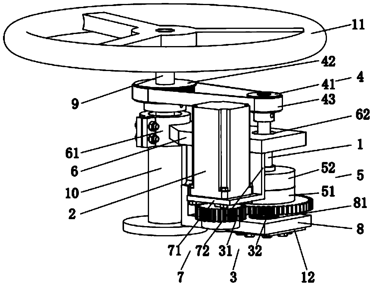
[0044] figure 1 It is a structural schematic diagram of an automatic steering wheel control device provided in Embodiment 1 of the present invention.

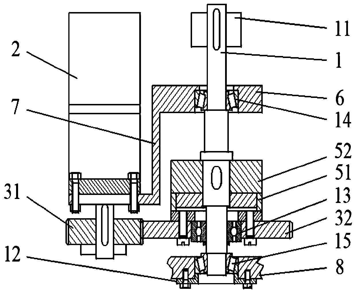
[0045] figure 2 It is a schematic cross-sectional view of an automatic steering wheel control device provided in Embodiment 1 of the present invention.

[0046] Please refer to figure 1 , figure 2, The present invention provides an automatic steering wheel control device, including: an intermediate shaft 1, a motor 2, a first transmission mechanism 3, a second transmission mechanism 4, and an electromagnetic clutch 5.

[0047] The intermediate shaft 1 is arranged on one side of the steering wheel axis 9 and is parallel to the steering wheel axis 9 .

[0048] The motor 2 is arranged on one side of the intermediate shaft 1 and is parallel to the intermediate shaft 1 .

[0049] Optionally, the motor 2 is a stepping motor, but the present invention is not limited thereto, and the motor 2 can also be other types of motors.

...

Embodiment 2

[0088] Figure 6 It is a flow chart of an installation method of an automatic steering wheel control device provided in Embodiment 2 of the present invention.

[0089] Please refer to Figure 6 , the invention provides a method for installing an automatic steering wheel control device, comprising the following steps:

[0090]S1, remove the steering wheel 11 from the steering wheel shaft 9, and saw off the steering wheel sleeve 10 with a preset length. Wherein, the preset length is the calculated length of the steering wheel sleeve 10 that should be cut off according to the installation requirements of the clamping portion 61 of the first fixing frame 6 .

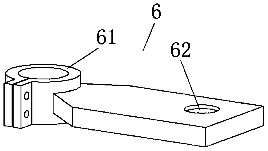
[0091] S2, using the clamping portion 61 of the first fixing bracket 6 to fix the first fixing bracket 6 on the steering wheel sleeve 10 . Specifically, bolts and nuts are used to fix the clamping portion 61 on the steering wheel sleeve 10 .

[0092] S3, fix the motor 2 on the motor fixing plate 71 of the second fixing f...


PUM


Abstract

The invention discloses an automatic steering wheel control device, and belongs to the technical field of engineering machinery. The automatic steering wheel control device comprises an intermediate shaft (1), a motor (2), a first transmission mechanism (3), a second transmission mechanism (4) and an electromagnetic clutch (5). The intermediate shaft (1) is arranged on a side of a steering wheel shaft (9), the motor (2) is positioned on a side of the intermediate shaft (1), the intermediate shaft (1) is connected with the motor (2) by the first transmission mechanism (3) and is connected withthe steering wheel shaft (9) by the second transmission mechanism (4), and the first transmission mechanism (3) is connected with the intermediate shaft (1) by the electromagnetic clutch (5); the intermediate shaft (1) can be driven by the motor (2) via the first transmission mechanism (3) and the electromagnetic clutch (5) to rotate, and the steering wheel shaft (9) can be driven by the intermediate shaft (1) via the second transmission mechanism (4) to rotate. The automatic steering wheel control device has the advantages that the transmission ratio can be increased by the automatic steeringwheel control device, high torque can be outputted, automatic steering wheel control and manual control can be flexibly switched over without mutual interference, the automatic steering wheel controldevice is compact in structure, only small mounting spaces are required, and the like.

Description

technical field [0001] The invention relates to the technical field of engineering machinery, in particular to an automatic steering wheel control device and an installation method thereof. Background technique [0002] Since the intelligentization of construction machinery can save working time and a large amount of labor expenditure to a certain extent, and improve labor production efficiency, it is advocated by the state. The modification of intelligent excavators in my country is still in its infancy. [0003] Traditional excavators need to be driven and controlled by humans. The characteristics of crawler driving make the excavator travel very slowly, and the long-term work transition will easily make the driver feel tired. With recent advances in intelligent technology, it has become a technological trend to free the driver's hands from the steering wheel. The traditional manned excavator allows the driver to fix his whole body on the steering wheel. The driver needs ...

Claims


Application Information

Patent Timeline
Patent Type & Authority Patents(China)
IPC IPC(8): B62D5/04
Inventor 刘成良陶建峰黄武涛刘颖郭隽侠李卫星杨泰春唐小涛
Owner SHANGHAI ALLYNAV TECH CO LTD
Learn More