
Baking tray support lifting mechanism for oven

A lifting mechanism and baking pan technology, applied in the directions of roaster/barbecue grid, stove/stove stand/shelf, baking device, etc., can solve the problem of difficulty in meeting, no self-locking function, and inability to achieve non-uniform lifting and lowering, etc. problem, to achieve the effect of high reliability and simple structure

Pending Publication Date: 2018-05-08
NINGBO FOTILE KITCHEN WARE CO LTD
View PDF0 Cites 16 Cited by
  • Summary
  • Abstract
  • Description
  • Claims
  • Application Information

AI Technical Summary

Problems solved by technology

Traditional ovens have several fixed positions for the installation of baking trays and grills according to the volume of the inner tank. Although they can meet the general cooking requirements, it is difficult to meet the needs of users who have higher requirements for baking effects.
[0003] Traditional lifting mechanisms include worm gear screw lifting mechanism, lead screw nut lifting mechanism, pinion and rack lifting mechanism, bevel gear lifting mechanism, belt chain lifting mechanism and chain lifting mechanism, etc. These lifting mechanisms can meet the function of uniform lifting, but It cannot be lifted at a non-uniform speed by itself. When some baked food needs to be lifted up and down in the oven liner at a non-uniform speed, these mechanisms cannot meet the demand
[0004] Traditional lifting mechanisms such as worm gear screw lifting mechanism and lead screw nut lifting mechanism have low efficiency; rack and pinion lifting mechanism and bevel gear lifting mechanism have no self-locking function; belt chain lifting mechanism and chain lifting mechanism are not high in accuracy, and The structures of these methods are relatively complex

Method used


Image

  • Baking tray support lifting mechanism for oven
  • Baking tray support lifting mechanism for oven
  • Baking tray support lifting mechanism for oven

Examples


Embodiment Construction

[0038] The present invention will be further described in detail below in conjunction with the accompanying drawings and embodiments.

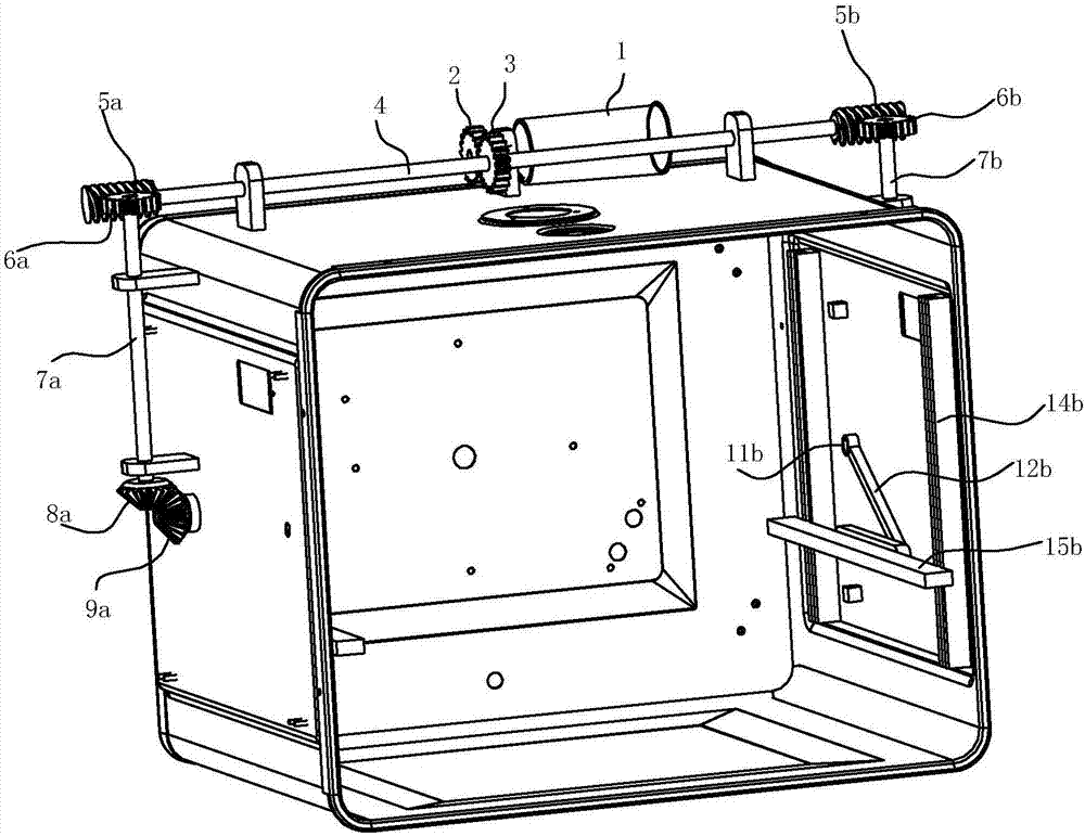
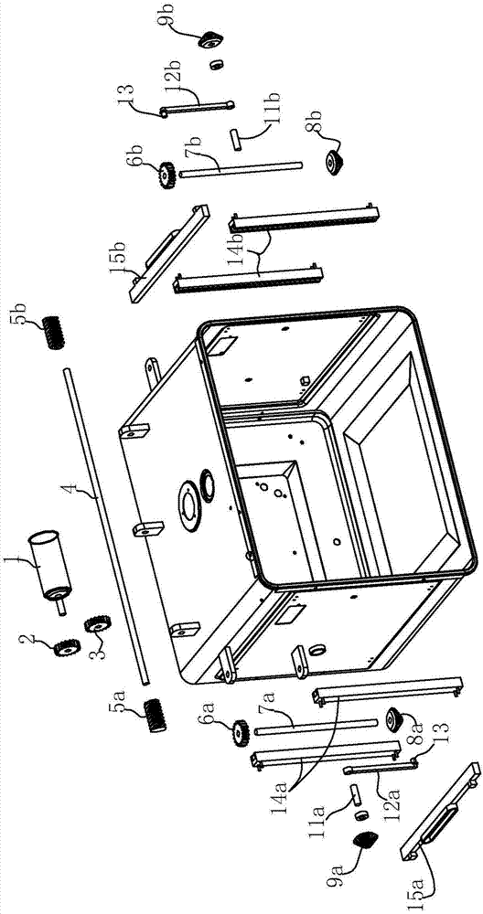
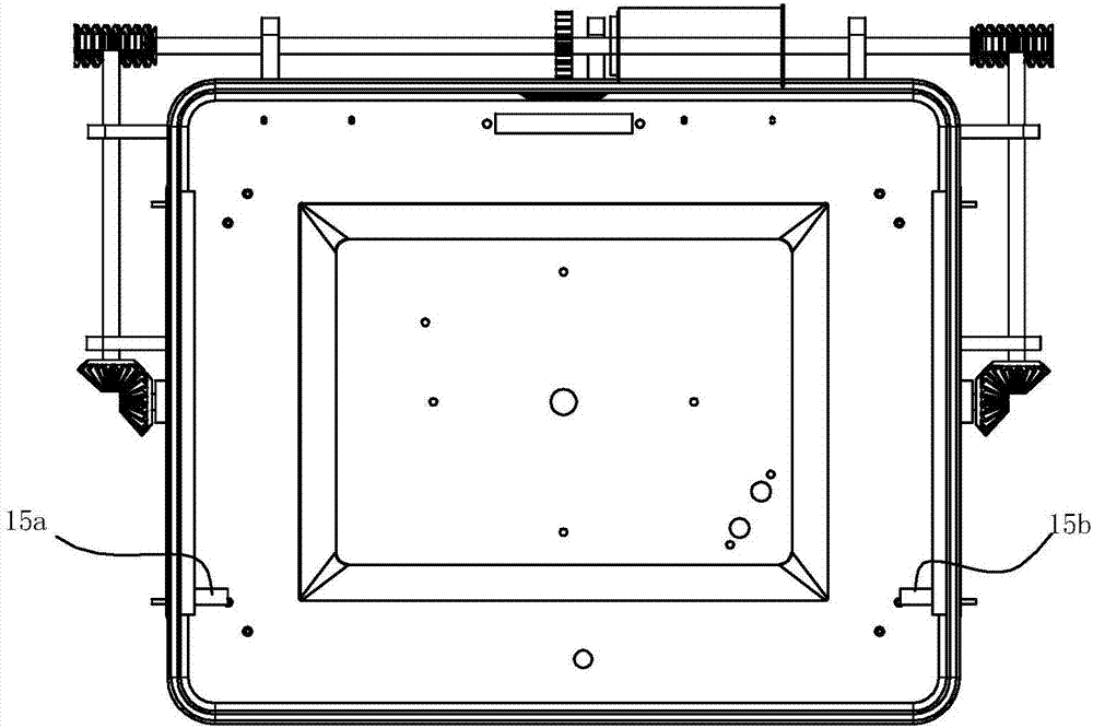
[0039] Such as Figure 1~5 The baking pan support lifting mechanism of the oven shown is connected with the left baking pan support 15a and the right baking pan support 15b arranged on the left and right sides of the oven liner for supporting the baking pan, and is used to drive the left baking pan support and the right baking pan support. The pan support moves up and down in the oven liner, which includes

[0040] The driving motor 1 is installed on the motor mounting base, and the motor mounting base is installed above the outside of the oven liner;

[0041] The first gear 2 is connected with the output shaft of the driving motor 1;

[0042] The second gear 3 meshes with the first gear 2 and is fixed at the middle position of the synchronous shaft 4, the synchronous shaft 4;

[0043] The first worm 5a is fixedly connected to the first end...


PUM


Abstract

The invention relates to a baking tray support lifting mechanism for an oven. The mechanism is connected with a left baking tray support and the right baking tray support which are arranged on the left side and the right side of an inner container of the oven and used for supporting baking trays, and used for driving the left baking tray support and the right baking tray support to move up and down in the inner container of the oven; the mechanism is characterized by comprising a driving motor, a first gear, a second gear, a first worm, a second worm, a left transmission shaft, a third gear, first left conical teeth, second conical teeth, a left crank, a right transmission shaft, a fourth gear, first right conical teeth, second right conical teeth and a right crank. Compared with the priorart, the mechanism has the advantages that the lifting mechanism is realized through a crank sliding block principle, static self-locking can be achieved for oven side support at different heights inthe inner container of the oven; the oven support can rise and fall according to a trigonometric function uninterruptedly, an unexpected effect is brought for cooking, the structure is simple, and the reliability is high.

Description

technical field [0001] The invention relates to a lifting mechanism for a baking pan support of an oven. Background technique [0002] The temperature difference at different heights in the oven liner is not exactly the same, and the best cooking effect will be obtained for different foods at their corresponding baking temperatures. Traditional ovens have several fixed positions for installing baking pans and grills according to the volume of the inner tank. Although it can meet general cooking requirements, it is difficult to meet the needs of users who have higher requirements for baking effects. [0003] Traditional lifting mechanisms include worm gear screw lifting mechanism, lead screw nut lifting mechanism, pinion and rack lifting mechanism, bevel gear lifting mechanism, belt chain lifting mechanism and chain lifting mechanism, etc. These lifting mechanisms can meet the function of uniform lifting, but It cannot be lifted at a non-uniform speed by itself. When some ba...

Claims


Application Information

Patent Timeline
Patent Type & Authority Applications(China)
IPC IPC(8): A47J37/06A47J37/04
CPCA47J37/04A47J37/0664F24C15/16
Inventor 王黎喆杨均曹骥茅忠群诸永定
Owner NINGBO FOTILE KITCHEN WARE CO LTD
Learn More