
Compound energy storage system capacity configuration method and terminal equipment

A composite energy storage and system capacity technology, applied in the field of composite energy storage system capacity configuration method and terminal equipment, can solve problems such as complex calculation, weak theory, poor adaptability and feasibility

Active Publication Date: 2018-05-04
囯网河北省电力有限公司电力科学研究院 +2
View PDF5 Cites 8 Cited by
  • Summary
  • Abstract
  • Description
  • Claims
  • Application Information

AI Technical Summary

Problems solved by technology

[0007] In view of this, the embodiment of the present invention provides a method for configuring the capacity of a composite energy storage system and terminal equipment to solve the problem that most of the methods for configuring the capacity of a multivariate composite energy storage system in the prior art are based on empirical analysis, which is weak in theory and complex in calculation. , the problem of poor adaptability and feasibility

Method used


Image

  • Compound energy storage system capacity configuration method and terminal equipment
  • Compound energy storage system capacity configuration method and terminal equipment
  • Compound energy storage system capacity configuration method and terminal equipment

Examples


Embodiment 1

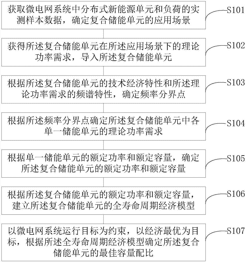
[0075] Such as figure 1 As shown, it is a flow chart of the steps of the method for configuring the capacity of the composite energy storage system provided by the embodiment of the present invention, including:

[0076] In step S101, the measured sample data of distributed new energy units and loads in the microgrid system are obtained, and the application scenario of the composite energy storage unit is determined.

[0077] Specifically, in the microgrid system, the energy storage system is often used to maintain the voltage and frequency stability of the microgrid. The energy storage system can stabilize the power fluctuations in the microgrid, ensure the stable operation of the microgrid system, and absorb distributed new The output power of energy, to solve the problem of the installation penetration rate of distributed new energy, when determining the optimal capacity configuration of the composite energy storage system, it is first necessary to obtain the measured sampl...

Embodiment 2

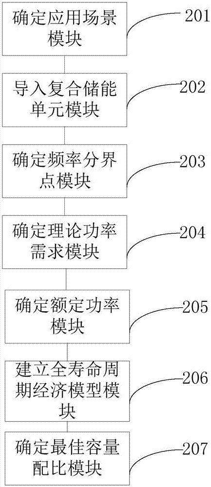
[0129] Such as figure 2 As shown, it is a schematic structural diagram of the capacity configuration device of the composite energy storage system provided by the embodiment of the present invention, including:

[0130] Determine the application scenario module 201, which is used to obtain the measured sample data of distributed new energy units and loads in the microgrid system, and determine the application scenario of the composite energy storage unit;

[0131] importing the composite energy storage unit module 202, for obtaining the theoretical power demand of the composite energy storage unit in the application scenario, and importing the composite energy storage unit;

[0132] Determining a frequency demarcation point module 203, configured to determine a frequency demarcation point according to the technical and economic characteristics of the composite energy storage unit and the spectral characteristics of the theoretical power demand;

[0133] Determine a theoretic...

Embodiment 3

[0139] Such as image 3 As shown, it is a schematic structural diagram of the capacity configuration device of the composite energy storage system provided by the embodiment of the present invention, including:

[0140] Determine the application scenario module 301, which is used to obtain the measured sample data of distributed new energy units and loads in the microgrid system, and determine the application scenario of the composite energy storage unit;

[0141] Importing a composite energy storage unit module 302, for obtaining the theoretical power demand of the composite energy storage unit in the application scenario, and importing the composite energy storage unit;

[0142] Determining a frequency demarcation point module 303, configured to determine a frequency demarcation point according to the technical and economic characteristics of the composite energy storage unit and the spectral characteristics of the theoretical power demand;

[0143] Determine a theoretical ...


PUM


Abstract

The invention is applicable to the technical field of distributed power generation, and particularly relates to a compound energy storage system capacity configuration method and terminal equipment. The method comprises the steps of obtaining a theoretical power requirement of a compound energy storage unit under an application scene, and importing the compound energy storage unit; determining a frequency demarcation point according to technical and economic features and theoretical power requirements of the compound energy storage unit; according to the frequency demarcation point, determining theoretical power requirements of all single energy storage units in the compound energy storage unit; building a full-life-cycle economic model of the compound energy storage unit according to rated power and rated capacity of the single energy storage units; determining the optimum capacity matching ratio of the compound energy storage unit according to the entire-life-cycle economic model. According to the technical scheme, the entire-life-cycle economic model determines the optimum capacity matching ratio of the compound energy storage unit, the determination is not simply based on empirical anymore, the theoretical property is good, calculation is simple and accurate, and the method has very high applicability and feasibility.

Description

technical field [0001] The invention belongs to the technical field of distributed power generation, and in particular relates to a capacity configuration method and terminal equipment of a composite energy storage system. Background technique [0002] A microgrid is a small regional power grid that includes various forms of new energy, gas turbines, diesel generators, loads, etc. The microgrid solves the grid-connection problem of distributed new energy, and at the same time can ensure the power supply of more important loads during power outage maintenance of the distribution network, which improves the power supply reliability of the system and is the development of distributed new energy access to the distribution network. trend. At present, domestic and foreign microgrids are in the initial and development stage. [0003] In the microgrid, energy storage systems are mostly used to maintain the voltage and frequency stability of the microgrid. The energy storage syste...

Claims


Application Information

Patent Timeline
Patent Type & Authority Applications(China)
IPC IPC(8): H02J3/28G06Q10/06G06Q50/06
CPCG06Q10/06315G06Q50/06H02J3/28Y02E40/70Y04S10/50
Inventor 孟良杨潇范辉胡文平张福东李均强
Owner 囯网河北省电力有限公司电力科学研究院
Learn More