Elastic modulus test method based on virtual pure bending material
A technology of elastic modulus and testing method, which is applied in the field of elastic modulus testing based on virtual pure bending materials, can solve problems such as the inability to achieve modulus measurement, achieve short test time, long time-consuming, and avoid tediousness Effect
- Summary
- Abstract
- Description
- Claims
- Application Information
AI Technical Summary
Problems solved by technology
Method used
Image
Examples
Embodiment 1
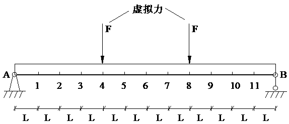
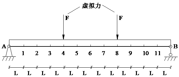
[0029] Example 1: simply supported beam member
[0030] combine figure 1 For the slender simply supported beam member shown, the procedure for measuring the elastic modulus of the material is as follows:
[0031] (1) Install 11 sensors at equal intervals at the bottom of the beam member, conduct a free vibration modal test, and obtain the first m-order modal parameters of the free vibration of the member, that is, the circular frequency ω j and mode shape φ j , the approximate flexibility matrix F of the component is calculated from the obtained data using the formula (1), and the calculation formula of the approximate flexibility matrix F of the component is:
[0032] (2) Construct the corresponding virtual force vector l according to the support constraints of the component v ,for figure 1 For the simply supported beam member shown, for the section between nodes 4 and 8, the constructed virtual force vector is l v =[0,0,0,F,0,0,0,F,0,0,0] T , that is, a virtual conce...
Embodiment 2
[0035] Example 2: Cantilever beam member
[0036] combine figure 2 For the slender cantilever beam member shown, the procedure for measuring the elastic modulus of the material is as follows:
[0037] (1) Install 12 sensors at equal intervals at the bottom of the beam member, conduct a free vibration modal test, and obtain the first m-order modal parameters of the free vibration of the member, that is, the circular frequency ω j and mode shape φ j , the approximate flexibility matrix F of the component is calculated from the obtained data using the formula (1), that is, the calculation formula of the approximate flexibility matrix F of the component is:
[0038] (2) Construct the corresponding virtual force vector l according to the support constraints of the component v ,for figure 2 For the straight-bar cantilever beam member of constant section shown, for the section between nodes A and 8, the constructed virtual force vector is lv =[0,0,0,0,0,0,0,F,0,0,0,-F] T , t...
PUM
 Abstract
Description
Claims
Application Information
 - R&D
- Intellectual Property
- Life Sciences
- Materials
- Tech Scout
- Unparalleled Data Quality
- Higher Quality Content
- 60% Fewer Hallucinations
Browse by: Latest US Patents, China's latest patents, Technical Efficacy Thesaurus, Application Domain, Technology Topic, Popular Technical Reports.
© 2025 PatSnap. All rights reserved.Legal|Privacy policy|Modern Slavery Act Transparency Statement|Sitemap|About US| Contact US: help@patsnap.com


