Oil hot air furnace with intelligent control terminal

An intelligent control, hot blast stove technology, used in air heaters, fluid heaters, lighting and heating equipment, etc., can solve the problems of starting and stopping the boiler burner, no stable transition process, increasing the volume of the boiler control system, etc. achieve the effect of ensuring stability

Inactive Publication Date: 2018-05-01
河南飞防兵科技有限公司
View PDF6 Cites 2 Cited by
  • Summary
  • Abstract
  • Description
  • Claims
  • Application Information

AI Technical Summary

Problems solved by technology

It can also be used in the heating of factories, auditoriums, farm sheds, livestock houses and other buildings, as well as the dehumidification or heating process of underground mining areas, underground engineering and other places. People have higher and higher requirements for the automation of boiler equipment; Most furnaces have control devices. When the hot air temperature reaches the upper limit of the rated temperature, the burner will automatically stop burning to reduce the temperature. When the hot air temperature drops to the rated off-line temperature, the burner will burn again, but this will cause hot air The temperature fluctuates, there is no stable process
[0003] The control system of the oil-fired gas hot blast stove in the prior art requires the cooperation of high-intensity labor and uninterrupted implementation of supervision and control. Unstable boiler load is likely to cause frequent start and stop of boiler burners. less than expected effect
The hot air temperature of the boiler cannot be automatically controlled, and other temperature controllers need to be added, which also increases the volume of the boiler control system

Method used


Image

  • Oil hot air furnace with intelligent control terminal
  • Oil hot air furnace with intelligent control terminal

Examples


Embodiment

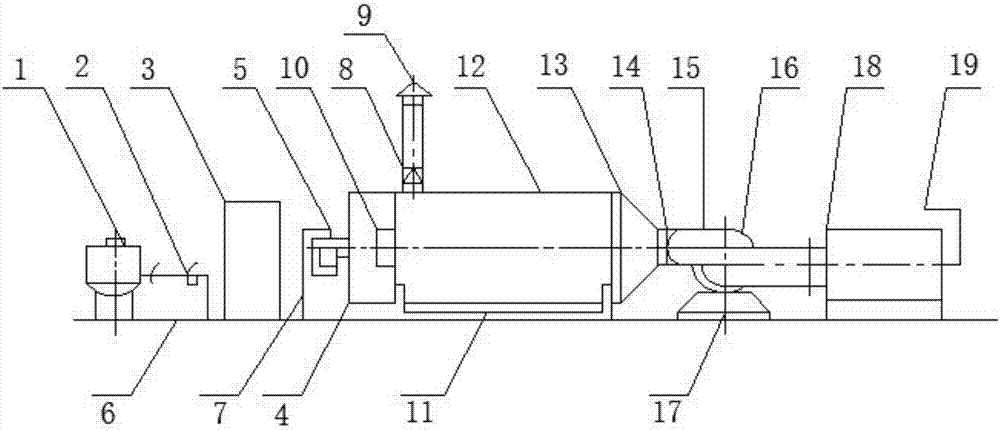
[0017] see Figure 1-2 , the present invention provides a technical solution: a fuel-fired hot air stove with an intelligent control terminal, including an oil storage tank 1, a main valve oil filter 2, a control box 3, a burner 4, an oil pipe 6, an oil inlet pipe 7, a chimney 9, Hot air outlet 10, heat exchanger 12, air inlet cover 13, air blower 16, air filter 18 and cold air inlet 19; the oil pipe 6 is laid on the access opening of the fuel hot blast stove; the oil storage tank 1 and the main valve filter oil The oil filter 2 is connected through the oil pipe 6, and the control box 3 is arranged on the right side of the main valve oil filter 2; the left port of the heat exchanger 12 is connected to the burner 4, and the right port is connected to the air inlet cover 13, and the bottom of the heat exchanger 12 is provided with a Seat 11, a burner seat 5 is provided at the bottom of the burner 4, and a hot air outlet 10 is provided at the connection with the burner 4; the bur...


PUM


Abstract

The invention discloses an oil hot air furnace with an intelligent control terminal. The oil hot air furnace comprises an oil storage tank, a main valve oil filter, a control cabinet, a combustor, anoil pipe, an oil inlet pipe, a chimney, a hot air outlet, a heat exchanger, an air inlet cover, an air blower, an air filter and a cold air inlet; the oil pipe is laid at a passage port of the oil hotair furnace; the oil storage tank is connected to the main valve oil filter through the oil pipe; the control cabinet is arranged on the right side of the main valve oil filter; the combustor is connected to a left port of the heat exchanger; the air inlet cover is connected to a right port of the heat exchanger; a machine base is arranged at the bottom of the heat exchanger; a combustor base isarranged at the bottom of the combustor; the heat exchanger communicates with the air blower through a connecting pipe; an air blower damping base is arranged at the bottom of the air blower; the right side of the air blower is connected to the air filter; and one side of the air filter is connected to the cold air inlet. The oil hot air furnace has the advantages that full-automatic control overthe device is carried out by utilizing the control cabinet, the hot air temperature of the heat exchanger and the hot air temperature of the combustor can be automatically controlled, and the stability of hot air temperature can be guaranteed.

Description

technical field [0001] The invention relates to the technical field of fuel-fired hot blast stoves, in particular to a fuel-fired hot blast stove with an intelligent control terminal. Background technique [0002] Hot air stove is widely used in drying, spraying and dehydration of various materials such as chemical industry, food, medicinal materials, tobacco, ceramics and building materials. It can also be used for heating of buildings such as workshops, auditoriums, farm sheds, and livestock houses, as well as for dehumidification or heating processes in underground mining areas, underground engineering, etc. People have higher and higher requirements for the automation of boiler equipment; Most furnaces have control devices. When the hot air temperature reaches the upper limit of the rated temperature, the burner will automatically stop burning to reduce the temperature. When the hot air temperature drops to the rated off-line temperature, the burner will burn again, but ...

Claims


Application Information

Patent Timeline
Patent Type & Authority Applications(China)
IPC IPC(8): F24H3/00F24H9/20F24H9/18
CPCF24H3/006F24H9/1881F24H9/2085
Inventor 王飞
Owner 河南飞防兵科技有限公司
Why Eureka
Try Eureka