Cracking furnace

A cracking furnace and radiant furnace tube technology, which is used in cracking, hydrocarbon cracking to produce hydrocarbons, and non-catalytic thermal cracking, etc., can solve problems such as affecting the reaction of cracking raw materials, inconsistency in furnace tube length or structure, etc., to improve the arrangement method and reduce the layout. Difficulty and small footprint

Active Publication Date: 2018-05-01
CHINA PETROLEUM & CHEM CORP +1
View PDF6 Cites 2 Cited by
  • Summary
  • Abstract
  • Description
  • Claims
  • Application Information

AI Technical Summary

Problems solved by technology

[0007] Furnace tubes are arranged in the same plane. For the two-pass furnace tubes widely used in cracking furnaces, it is necessary to connect the inlet and outlet pipes. Arranging on the same plane will undoubtedly bring each group of furnace tubes Tubes (consisting of an inlet tube and an outlet tube) cross each other, resulting in inconsistent length or structure of each group of furnace tubes, resulting in slight differences in the structure of the furnace tubes, which in turn affects the reaction of cracking raw materials in the furnace tubes

Method used


Image

  • Cracking furnace
  • Cracking furnace
  • Cracking furnace

Examples


Embodiment 1

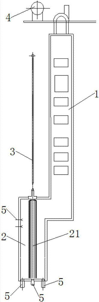
[0054] use figure 1 The cracking furnace shown carries out the cracking reaction. The specific process includes:

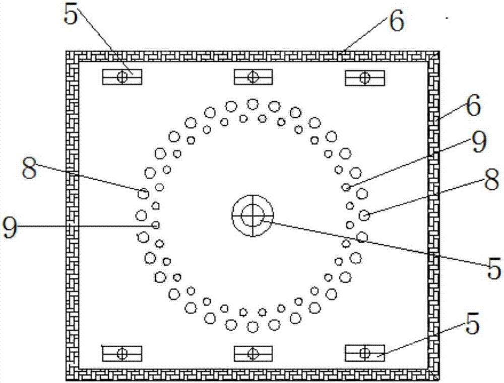
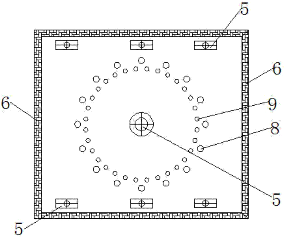
[0055] Naphtha at 60°C is gasified and preheated in the convection section 2 and then enters the furnace tube 3 of the radiant section for cracking reaction. The combustion system of the radiant section 5 adopts the combination of bottom burner and side wall burner. The heat supply ratio is 80%; the temperature at which naphtha is preheated in the convection section, that is, the cross-over temperature (XOT) of the cracking furnace is 590°C, the outlet temperature (COT) of the radiant section of the cracking furnace is 830°C, and the furnace tube in the radiant section is 3 A single-pass furnace tube is adopted, the inlet diameter of the furnace tube is 41mm, the outlet diameter of the furnace tube is 53mm, the length of the furnace tube is 12.8m, and the furnace tube adopts bottom entry and top exit. Furnace tube arrangement as Figure 4 Arranged in a new way ...


PUM


Abstract

The invention discloses a cracking furnace. The cracking furnace comprises a convection section, a radiation section communicated with the convection section, a quenching boiler and a steam drum, wherein the convection section is internally provided with a convection tube bundle communicated with a feed inlet of the cracking furnace; the steam drum is arranged on the top of the convection section;the top of the convection section is provided with a fan communicated with the cracking furnace; the radiation section is internally provided with a plurality of groups of radiation tube bundles; theradiation tube bundles comprise a plurality of radiation furnace tubes; the plurality of radiation furnace tubes are arranged along the peripheries of the radiation tube bundles at intervals; the radiation furnace tubes are communicated with the convection tube bundle; the bottom and sidewall of a hearth in the radiation section are separately provided with a plurality of combustors; and the outlet ends of the radiation furnace tubes are communicated with the quenching boiler. The cracking furnace provided by the invention is simple in structure; through improvement of the arrangement mode ofthe radiation furnace tubes, difficulties in arrangement of the radiation furnace tubes can be reduced, and reaction conditions in each group of radiation furnace tubes in the cracking furnace are maximally maintained same; and the cracking furnace has the advantage of a small occupied land area under the condition of same unit production capacity.

Description

technical field [0001] The invention relates to the technical field of petroleum hydrocarbon steam cracking with tube furnaces, in particular to a cracking furnace. Background technique [0002] Low-carbon olefins such as ethylene, propylene and butadiene are important basic raw materials for the petrochemical industry. At present, the method for producing low-carbon olefins is mainly based on the tube furnace petroleum hydrocarbon steam cracking process. According to statistics, about 99% of ethylene, more than 50% of propylene and more than 90% of butadiene in the world are produced through this process. [0003] The core equipment of the tubular furnace petroleum hydrocarbon steam cracking process is the tubular cracking furnace (hereinafter referred to as the "cracking furnace"). When the cracking raw materials such as ethane, propane, naphtha and hydrogenated tail oil are heated to high temperature in the cracking furnace , a carbon chain scission chemical reaction wi...

Claims


Application Information

Patent Timeline
Patent Type & Authority Applications(China)
IPC IPC(8): C10G9/20C07C4/04C07C11/04C07C11/06C07C11/16
CPCC07C4/04C10G9/20C10G2300/1037C10G2300/1081C10G2400/20C07C11/04C07C11/06C07C11/16
Inventor 张利军周丛王国清杜志国张永刚张兆斌刘俊杰
Owner CHINA PETROLEUM & CHEM CORP
Why Eureka
Try Eureka