Material conveying device and spiral conveying part for material conveying device

A conveying device and screw conveying technology, which is applied to mixers with rotating stirring devices, conveyors, transportation and packaging, etc., can solve the problems of poor material conveying fluency and low conveying efficiency, and achieve reasonable setting size and improve conveying The effect of efficiency and conveying smoothness

Active Publication Date: 2018-05-01
GUANGDONG MIDEA KITCHEN APPLIANCES MFG CO LTD +1
View PDF9 Cites 4 Cited by
  • Summary
  • Abstract
  • Description
  • Claims
  • Application Information

AI Technical Summary

Problems solved by technology

[0003] In related technologies, there is no clear size and ratio for the blade size of the conveying part. When the blade size of the conveying part is set unreasonably, the conveying efficiency of the blade conveyed material is low, and the conveying fluency of the material is poor, and the conveying efficiency is low.

Method used


Image

  • Material conveying device and spiral conveying part for material conveying device
  • Material conveying device and spiral conveying part for material conveying device
  • Material conveying device and spiral conveying part for material conveying device

Examples


Embodiment Construction

[0040] Embodiments of the present invention are described in detail below, examples of which are shown in the drawings, wherein the same or similar reference numerals designate the same or similar elements or elements having the same or similar functions throughout. The embodiments described below by referring to the figures are exemplary and are intended to explain the present invention and should not be construed as limiting the present invention.

[0041] In describing the present invention, it is to be understood that the terms "centre", "length", "upper", "lower", "top", "bottom", "inner", "outer", "axial", The orientation or positional relationship indicated by "radial", "circumferential", etc. is based on the orientation or positional relationship shown in the drawings, and is only for the convenience of describing the present invention and simplifying the description, rather than indicating or implying the referred device or element Must be in a particular orientation,...


PUM


Abstract

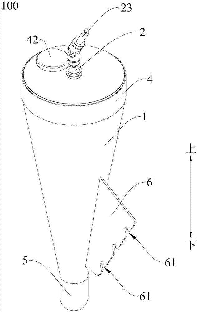
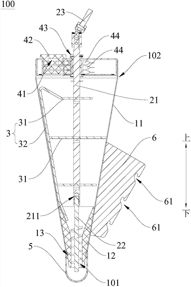
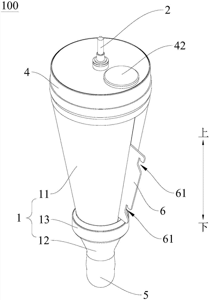
The invention discloses a material conveying device and a spiral conveying part for the material conveying device. The material conveying device comprises a hopper, a transmission assembly and a stirring assembly. The upper end of the hopper is a feeding end, and the lower end of the hopper is a discharging end. The transmission assembly is at least partially arranged in the hopper and can rotatearound the center axis of the transmission assembly. The transmission assembly comprises a transmission shaft and the spiral conveying part. The spiral conveying part is detachably connected to the lower end of the transmission shaft, and the spiral conveying part is at least partially located in the discharging end. The spiral conveying part comprises a rod part and a spiral blade arranged on therod part, the pitch of the spiral blade is P, the thickness of the spiral blade is T, the inner width of the spiral blade is W, the height of the spiral blade is H, wherein W is equal to the difference of P and T, and W is larger than H. According to the material conveying device, the material conveying efficiency and conveying smoothness are improved.

Description

technical field [0001] The invention relates to a conveying device, in particular to a material conveying device and a screw conveying part for the material conveying device. Background technique [0002] In the related art, the material conveying device includes a hopper, and a transmission shaft is arranged in the hopper, and the lower end of the transmission shaft is provided with a conveying part. The conveying part can be located at the discharge port of the material conveying device. There are blades on which the material can be placed, and the blade can rotate to convey the material out of the outlet. By changing the rotation speed of the drive shaft, the speed of the conveying part can be changed, thereby changing the flow rate of the material from the outlet. [0003] In related technologies, there is no clear size and ratio for the blade size of the conveying part. When the blade size of the conveying part is set unreasonably, the conveying efficiency of the blade ...

Claims


Application Information

Patent Timeline
Patent Type & Authority Applications(China)
IPC IPC(8): B65G65/46B65G33/26B01F7/20B01F27/906
CPCB65G33/265B65G65/463B65G2201/04B01F27/906B01F2101/00
Inventor 董永军许世猛李扬唐相伟
Owner GUANGDONG MIDEA KITCHEN APPLIANCES MFG CO LTD
Why Eureka
Try Eureka