High-voltage line deicing device convenient for identification

An easy-to-identify technology for high-voltage wires, applied in the installation of cables, electrical components, overhead installations, etc., can solve problems such as broken high-voltage wires, impact on production and life, and paralysis of photographed areas, so as to prolong service life and save manpower input , the effect of reducing the risk

Inactive Publication Date: 2018-04-27
GUANGXI NANNING SHENGQIAN TECH DEV CO LTD
View PDF6 Cites 0 Cited by
  • Summary
  • Abstract
  • Description
  • Claims
  • Application Information

AI Technical Summary

Problems solved by technology

[0002] Every winter, most provinces and regions in southern my country will encounter ice and snow disasters. Many high-voltage power lines are crushed due to too much ice accumulation, or become paralyzed in the area, resulting in large-scale power outages, which have a great impact on production and life.
The existing deicing technology mainly adopts manual beating, aircraft spraying ice-melting agent, etc. In addition, there are methods such as coating special materials on the outside of high-voltage wires, but these methods are unsafe, low in efficiency, and high in cost
Many existing technologies wait until the high-voltage wires are frozen to remove the ice, which increases the difficulty of cleaning. Now it is necessary to design a model that can be installed on the wires for a long time to automatically de-ice or prevent wires from freezing. ice effect device

Method used


Image

  • High-voltage line deicing device convenient for identification
  • High-voltage line deicing device convenient for identification

Examples


Embodiment 1

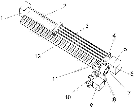
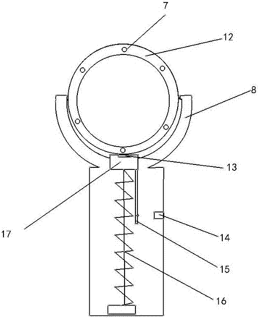
[0021] Such as figure 1As shown, an easily identifiable high-voltage wire deicing device includes a rotating device, a cutting device and a trigger device; the rotating device includes a sleeve 12, a driving gear 10, a driven gear 6, a sliding sleeve 11 and a motor three 9; The sleeve 12 is provided with a heating wire 7; the sleeve 12 wraps the high-voltage wires and has intervals between them; the sleeve 12 is arranged on the support rod 8; the sleeve 12 and The grooves of the support rod 8 are partially in contact; the inner interlayer of the sleeve 12 is provided with a plurality of heating wires 7; the heating wires 7 are arranged in the interlayer of the sleeve 12 in an encircling manner and are spaced from each other; Described drive gear 10 is located on motor three 9; Described drive gear 10 is positioned at the side of sleeve 12; Described driven gear 6 is fixed on the sliding sleeve 11; Described driven gear 6 and support bar There is a space between 8; there is a ...

Embodiment 2

[0024] Such as figure 1 As shown, an easily identifiable high-voltage wire deicing device includes a rotating device, a cutting device and a trigger device; the rotating device includes a sleeve 12, a driving gear 10, a driven gear 6, a sliding sleeve 11 and a motor three 9; The sleeve 12 is provided with a heating wire 7; the sleeve 12 wraps the high-voltage wires and has intervals between them; the sleeve 12 is arranged on the support rod 8; the sleeve 12 and The grooves of the support rod 8 are partially in contact; the inner interlayer of the sleeve 12 is provided with a plurality of heating wires 7; the heating wires 7 are arranged in the interlayer of the sleeve 12 in an encircling manner and are spaced from each other; Described drive gear 10 is located on motor three 9; Described drive gear 10 is positioned at the side of sleeve 12; Described driven gear 6 is fixed on the sliding sleeve 11; Described driven gear 6 and support bar There is a space between 8; there is a...

Embodiment 3

[0027] The third embodiment is basically the same in structure and principle as the first embodiment, except that the resistance wire 3 is replaced by other heatable metal wires, which can still achieve the purpose of the present invention.


PUM


Abstract

The invention discloses a high-voltage line deicing device convenient for identification, including a rotating device, a cutting device and a trigger device. The rotating device includes a sleeve, a driving gear, a driven gear, a sliding bush and a motor III. The cutting device includes a resistance wire, a resistance box, a steel wire rope, a motor I and a motor II. The trigger device includes asupport rod, an ejector block, a pressure sensor, a position sensor, a connecting rod and a spring column. By setting a transmission device on a line and setting a cutting device on the transmission device, the purpose of automatic and efficient high-voltage line deicing is achieved. The high-voltage line deicing device convenient for identification has the characteristics as follows: the device is highly practical and simple to use; the device can automatically and efficiently protect high-voltage lines from damage by external force; and the device prolongs the service life of high-voltage lines and saves human investment. The staff can easily and quickly identify the position of a high-voltage line and the working position of the deicing equipment in bad weather.

Description

technical field [0001] The invention belongs to the technical field of deicing, and relates to an easily identifiable high-voltage electric wire deicing device. Background technique [0002] Every winter, most provinces and regions in southern my country will encounter ice and snow disasters. Many high-voltage wires are crushed due to too much ice accumulation, or become paralyzed in the area, resulting in large-scale power outages, which have a great impact on production and life. Existing deicing technologies mainly use manual beating, spraying ice-melting agent on aircraft, etc. In addition, there are methods such as coating special materials on the outside of high-voltage wires, but these methods are unsafe, low in efficiency, and high in cost. Many existing technologies wait until the high-voltage wires are frozen to remove the ice, which increases the difficulty of cleaning. Now it is necessary to design a model that can be installed on the wires for a long time to aut...

Claims


Application Information

Patent Timeline
Patent Type & Authority Applications(China)
IPC IPC(8): H02G7/16
CPCH02G7/16
Inventor 钟安祺
Owner GUANGXI NANNING SHENGQIAN TECH DEV CO LTD
Why Eureka
Try Eureka