Display device

A display device and display panel technology, applied in nonlinear optics, instruments, optics, etc., can solve the problems of reduced display area, insufficient frame space, shadows, etc., and achieve the improvement of light leakage or shadow problems and the structural strength of extremely narrow frames Effect

Active Publication Date: 2018-04-27
INNOLUX CORP
View PDF6 Cites 4 Cited by
  • Summary
  • Abstract
  • Description
  • Claims
  • Application Information

AI Technical Summary

Problems solved by technology

However, when the above-mentioned structure is applied to the design of an extremely narrow bezel (the width of the bezel is, for example, 1mm), due to the insufficient space of the bezel, the plastic frame (plastic part) is located between the bezel and the display panel, and is used to connect the bezel The rubber mat with the display panel needs to extend into the pixel configuration area. Since the rubber mat is known to be made of opaque material, the area of ​​the display area is reduced, or light leakage or shadows are caused in the edge area of ​​the display area, which affects display screen

Method used


Image

  • Display device
  • Display device
  • Display device

Examples


Embodiment Construction

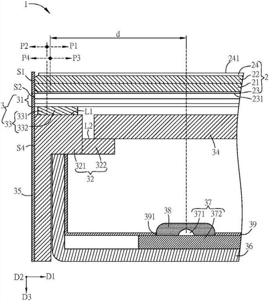
[0011] The following will describe display devices according to some embodiments of the present invention with reference to related drawings, wherein the same components will be described with the same reference symbols. The illustrations of all the implementation aspects of the technology of the present invention are only schematic representations, and do not represent actual dimensions and proportions. In addition, the orientations "up" and "down" in the following embodiments are only used to represent relative positional relationships. Furthermore, a device being formed "on", "over", "under" or "under" another device may include one device being in direct contact with another device in an embodiment, or may also include one device being in contact with another device. There are other additional devices between one device so that one device does not have direct contact with another device.

[0012] Please refer to figure 1 As shown, it is a schematic diagram of a display d...


PUM


Abstract

A display device comprises a bearing piece, a display panel, an optical film set and a light transmitting sticky piece. The bearing piece comprises a first supporting portion. The display panel is arranged on the bearing piece. The display panel comprises a pixel configuration region and a non-pixel configuration region, and the non-pixel configuration region is located on the periphery of the pixel configuration region. A part of the optical film set is arranged between the display panel and the first supporting portion of the bearing piece. The light transmitting sticky piece is arranged between the optical film set and the first supporting portion of the bearing piece, wherein the light transmitting sticky piece comprises a first portion and a second portion, the first portion corresponds to the non-pixel configuration region, and the second portion corresponds to the pixel configuration region, the display device can achieve the quite narrow frame and has the enough structural strength, and meanwhile the problem that light leak or shadow caused on the edge of a display region of a known display device can be solved.

Description

technical field [0001] The present invention relates to a display device, in particular to a display device with an extremely narrow frame design. Background technique [0002] With the advancement of technology, flat panel display devices have been widely used in various fields, especially liquid crystal display devices, which have gradually replaced traditional cathode ray tube display devices due to their superior characteristics such as light and thin body, low power consumption and no radiation. , and applied to many types of electronic products, such as mobile phones, portable multimedia devices, notebook computers, LCD TVs and LCD screens, etc. [0003] In the structural design of the current liquid crystal display module (including the display panel and the backlight module), the assembly and fixing method is to use plastic parts (such as plastic frames) to support the area other than the pixel configuration area of ​​​​the display panel, that is, the plastic parts a...

Claims


Application Information

Patent Timeline
Patent Type & Authority Applications(China)
IPC IPC(8): G02F1/1333
CPCG02F1/133308G02F1/133606G02F2202/28G02F1/133317G02F1/133528G02F1/133553
Inventor 陈胤霖郭子齐许玉凯颜仁祥
Owner INNOLUX CORP
Why Eureka
Try Eureka