Drain pump and clothes dryer

A technology for drainage pumps and clothes dryers, applied in the field of clothes dryers, which can solve the problems of reduced pump working capacity, increased residual water, and reduced pump flow, and achieves the effects of increasing drainage resistance, reducing flow loss, and ensuring performance parameters

Active Publication Date: 2019-11-22
WUXI LITTLE SWAN ELECTRIC CO LTD
View PDF4 Cites 0 Cited by
  • Summary
  • Abstract
  • Description
  • Claims
  • Application Information

AI Technical Summary

Problems solved by technology

But this will bring a problem at the same time, that is, when the drainage pump is working, the impeller rotates at a high speed, driving the water flow will be very strong, and part of the water will spew out from the vent hole. On the one hand, it will affect the electrical appliances above the pump On the other hand, if the opening is too large, the flow rate of the pump will be reduced, the residual water will increase, and the working capacity of the pump will be reduced.

Method used


Image

  • Drain pump and clothes dryer
  • Drain pump and clothes dryer
  • Drain pump and clothes dryer

Examples


Embodiment Construction

[0041] In order to understand the above-mentioned purpose, features and advantages of the present invention more clearly, the present invention will be further described in detail below in conjunction with the accompanying drawings and specific embodiments. It should be noted that, in the case of no conflict, the embodiments of the present application and the features in the embodiments can be combined with each other.

[0042] In the following description, many specific details are set forth in order to fully understand the present invention. However, the present invention can also be implemented in other ways than described here. Therefore, the protection scope of the present invention is not limited by the specific implementation disclosed below. Example limitations.

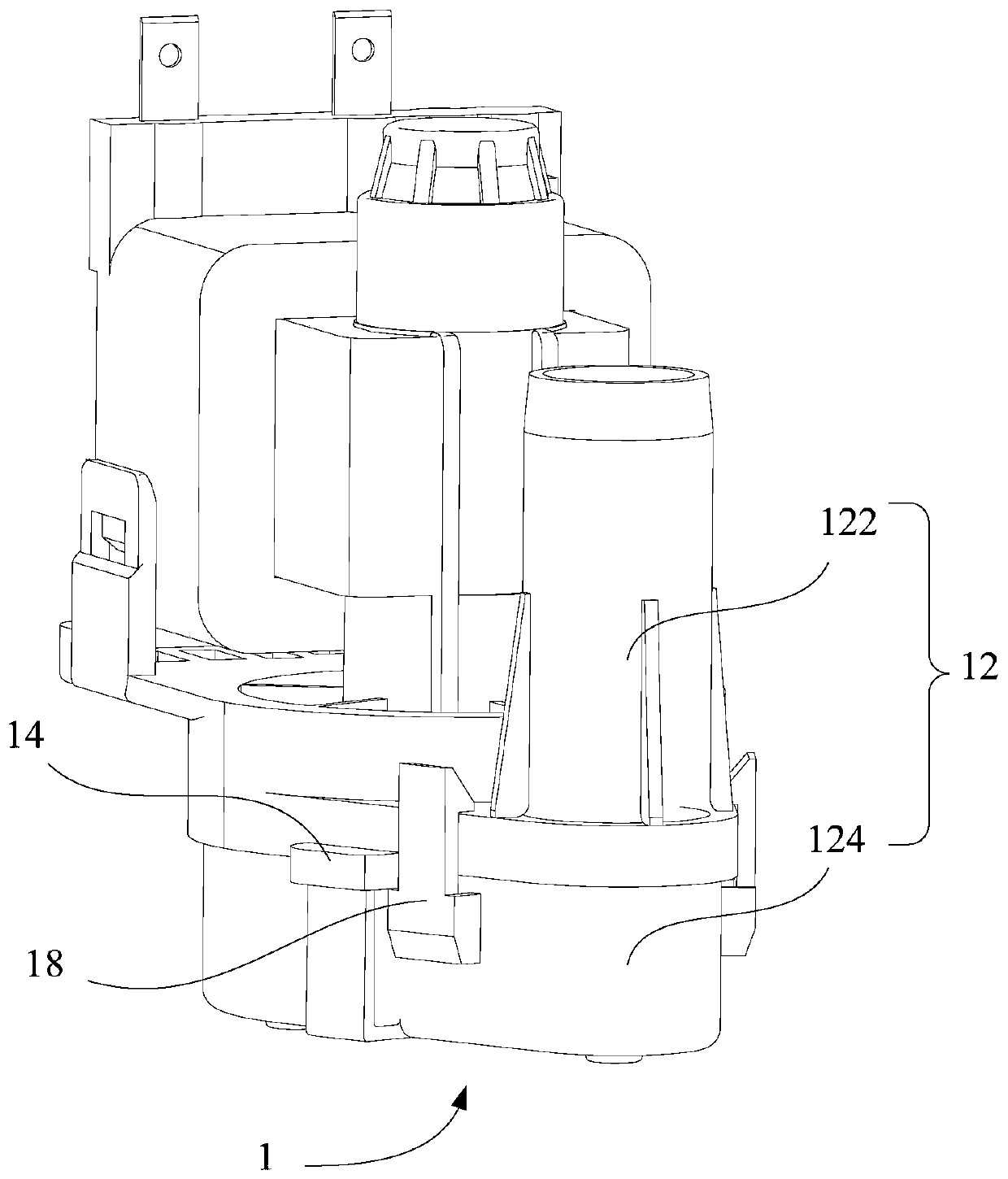
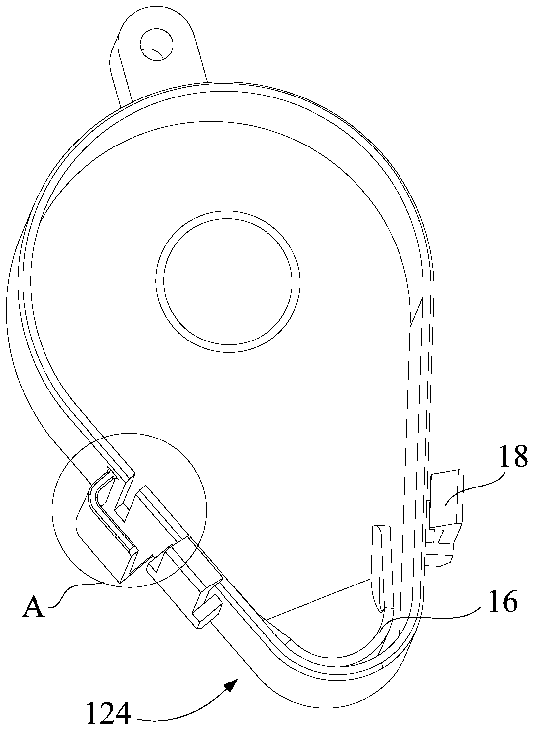
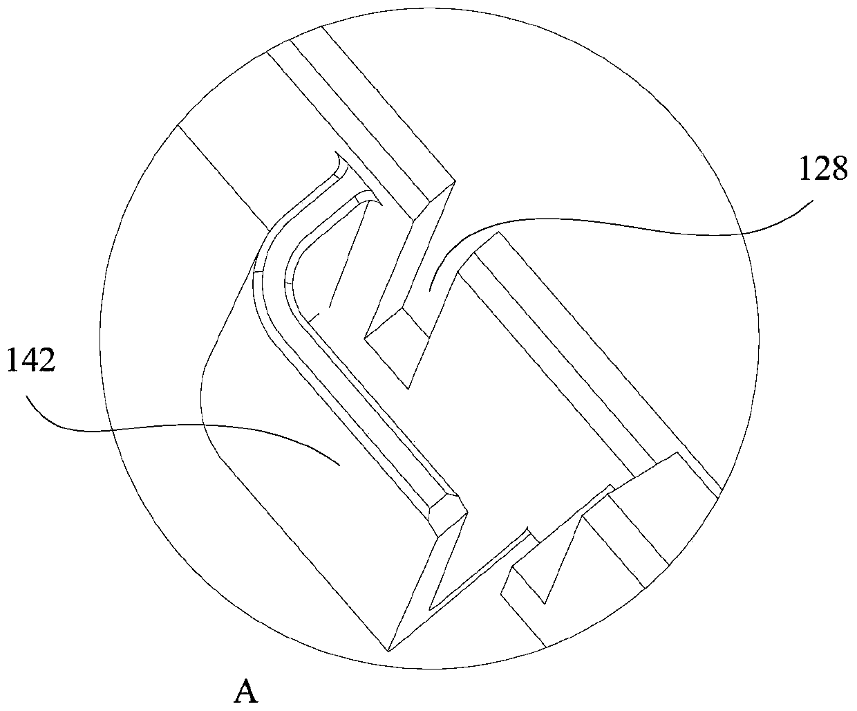
[0043] Refer below Figure 1 to Figure 5 The drain pump 1 and clothes dryer provided according to some embodiments of the present invention will be described.

[0044] The first aspect of the present invent...


PUM


Abstract

The invention provides a draining pump and a clothes dryer. The draining pump comprises a shell and an exhaust channel, wherein the shell is of a cavity structure with the side wall being provided with an exhaust opening; the exhaust channel is formed in the shell and located at the exhaust opening and is of a semi-closed structure with the side wall being provided with an opening; and the openingand the exhaust opening are different in orientation, and gas inside the shell is discharged out of the shell after passing through the exhaust opening and the exhaust channel. According to the draining pump, the exhaust opening is formed in the side wall of the shell, the exhaust channel is formed outside the shell and located at the exhaust opening, and the gas inside the shell is discharged out of the shell through the exhaust channel after passing through the exhaust opening, so that the problem that gas is trapped inside the shell is effectively solved; furthermore, when the gas is discharged through the exhaust channel, the gas needs to turn, and thus the draining resistance is increased; flow losses of the draining pump are reduced; performance parameters of the draining pump are guaranteed; and when the draining pump works, water cannot be splashed to electric parts above, and use safety of the draining pump is guaranteed.

Description

technical field [0001] The invention relates to the field of household appliances, in particular to a drainage pump and a clothes dryer. Background technique [0002] During the working process of the drainage pump, due to the reason of the drainage pipeline, the phenomenon of trapped air in the pump cavity often occurs, that is, the impeller inside the cavity cannot touch the water, and the impeller cannot pump the water out when it rotates, resulting in abnormal drainage. [0003] Existing solutions are often to open air vents on the top of the water pump cavity, so that the air inside the pump cavity is discharged from a higher place, and the water can fill the cavity in time to submerge the impeller to ensure normal water pumping. But this will bring a problem at the same time, that is, when the drainage pump is working, the impeller rotates at a high speed, and the force of driving the water flow will be great, and part of the water will spurt out from the vent hole. On...

Claims


Application Information

Patent Timeline
Patent Type & Authority Patents(China)
IPC IPC(8): F04D29/40F04D13/06D06F58/20
CPCD06F58/20F04D13/06F04D29/406
Inventor 周宇李学忠王飞龙
Owner WUXI LITTLE SWAN ELECTRIC CO LTD
Why Eureka
Try Eureka