
Conveying device

A transmission device and linear transmission technology, applied in the direction of conveyor objects, transportation and packaging, slideways, etc., can solve the problems of large workshop area, occupation, and increased production costs

Inactive Publication Date: 2018-04-27
GREE ELECTRIC APPLIANCES WUHAN +1
View PDF4 Cites 0 Cited by
  • Summary
  • Abstract
  • Description
  • Claims
  • Application Information

AI Technical Summary

Problems solved by technology

Take the conveying device that transports objects through the conveying device as an example. Usually, in order to prevent the objects on the conveying device from slipping, the design of the conveying route of the conveying device is limited by the climbing angle, and the design angle is generally less than 15°. At the same time, in order to meet the If the production needs, the length of the transmission device must be extended, thus occupying a larger workshop area and increasing the production cost

Method used

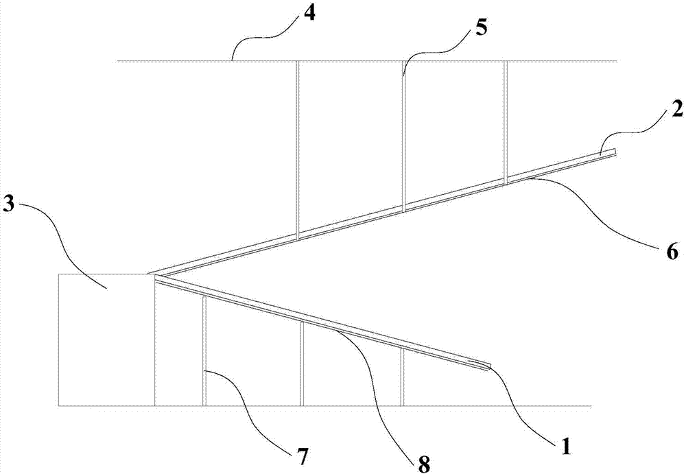
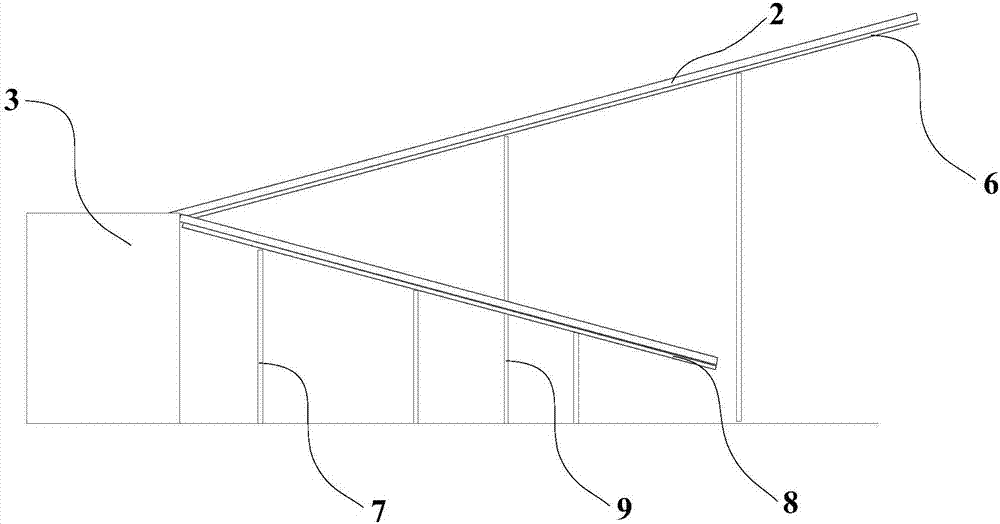
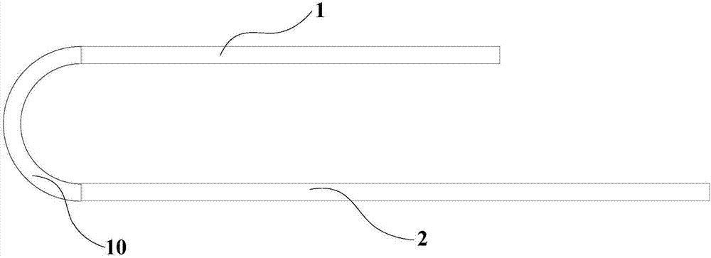

Image

  • Conveying device
  • Conveying device
  • Conveying device

Examples


Embodiment Construction

[0030] In order to make full use of the workshop space and reduce the production cost, the embodiment of the present invention provides a conveying device. In order to make the purpose, technical solution and advantages of the present invention clearer, the following examples are given to further describe the present invention in detail.

[0031] Such as Figure 1 to Figure 3 As shown, the transmission device provided by the embodiment of the present invention includes a first linear transmission mechanism 1, a second linear transmission mechanism 2 and a rotation mechanism 3, wherein,

[0032] The first linear transmission mechanism 1 includes a first feed end and a first discharge end; the second linear transmission mechanism 2 includes a second feed end and a second discharge end; the rotating mechanism 3 includes a horizontally arranged rotating portion 10, The rotating part 10 includes a third feeding end and a third discharging end, the first feeding end is opposite to ...


PUM


Abstract

The invention discloses a conveying device, accordingly, the plant space is sufficiently utilized, and the production cost is reduced. The conveying device comprises a first linear conveying mechanism, a second linear conveying mechanism and a rotating mechanism. The first linear conveying mechanism comprises a first feeding end and a first discharging end. The second linear conveying mechanism comprises a second feeding end and a second discharging end. The rotating mechanism comprises a horizontally-arranged rotation part. The rotation part comprises a third feeding end and a third discharging end, the first discharging end is opposite to the third feeding end, and the second feeding end is opposite to the third feeding end.

Description

technical field [0001] The invention relates to the technical field of transmission equipment, in particular to a transmission device. Background technique [0002] With the needs of industrial production, the equipment in the factory building is gradually increasing, so that the usable area in the factory building is constantly decreasing. Take the conveying device that transports objects through the conveying device as an example. Usually, in order to prevent the objects on the conveying device from slipping, the design of the conveying route of the conveying device is limited by the climbing angle, and the design angle is generally less than 15°. At the same time, in order to meet the If the production needs, the length of the transmission device must be extended, thereby occupying a larger workshop area and increasing the production cost. Contents of the invention [0003] The purpose of the embodiment of the present invention is to provide a conveying device to make ...

Claims


Application Information

Patent Timeline
IPC IPC(8): B65G11/02B65G47/52
CPCB65G11/02B65G47/52
Inventor 王硕王向红
Owner GREE ELECTRIC APPLIANCES WUHAN
Learn More