This helps you quickly interpret patents by identifying the three key elements:
Problems solved by technology
Method used
Benefits of technology
Problems solved by technology
This leads to an unsatisfactory extension of the structural length in the axial direction, which considerably limits the installation possibilities in vehicles
Method used
Image
Click on the blue label to locate the original text in one second.
Reading with bidirectional positioning of images and text.
Examples
Embodiment Construction
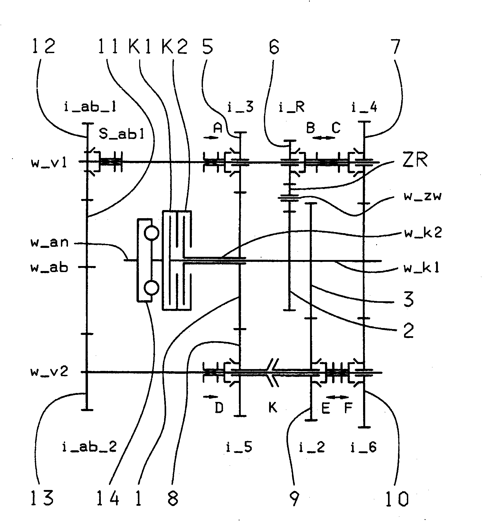
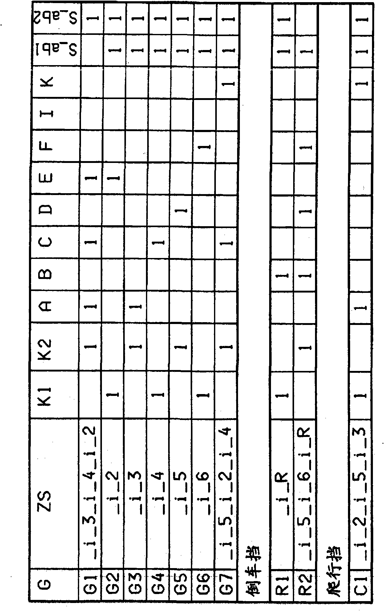
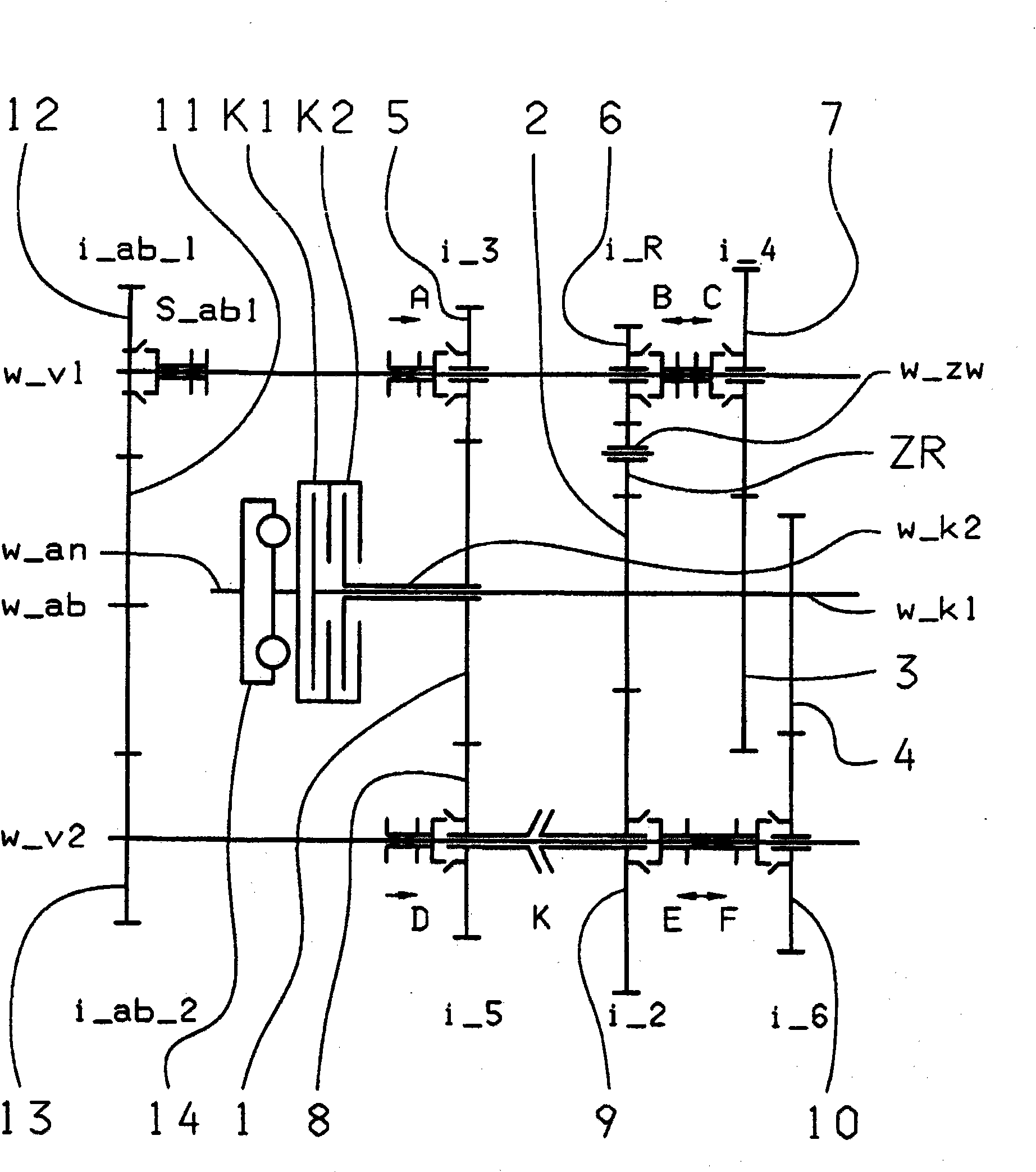
[0035] in the attached figure 1 , 3 , 5, 7 and 9 respectively show a possible implementation of the seven-speed dual-clutch transmission. The corresponding shift diagrams for each embodiment are in figure 2 , 4 , 6, 8 and 10 are shown graphically.
[0036] Regardless of the respective embodiment, the seven-speed dual-clutch transmission contains two clutches K1, K2, the inputs of which are connected to a drive shaft w_an and the outputs of which are each connected to two coaxially arranged transmissions One connection in the input shaft w_K1, w_K2. Furthermore, a torsional vibration damper 14 can be arranged on the drive shaft w_an. Furthermore, two countershafts w_v1 , w_v2 are provided, on which gearwheels formed as idler gears 5 , 6 , 7 , 8 , 9 , 10 are rotatably mounted. On the two transmission input shafts w_K1 , w_K2 , gearwheels formed as fixed gearwheels 1 , 2 , 3 , 4 are arranged in a rotationally fixed manner, said fixed gearwheels being at least partially con...
PUM
Abstract
The invention relates to a dual clutch transmission, with two dual gear planes (5-8, 7-10; 5-8, 6-9) being provided, one idler gear (5, 8; 6, 9; 7, 10) of the first and second countershafts (w_v1, w_v2) being associated with a fixed gear (1, 2, 3, 4) of one of the transmission input shafts (w_K1, w_K2) in every dual gear plane (5-8, 7-10; 5-8, 6-9), at least one idler gear (5, 6, 7, 8, 9, 10) in every dual gear plane (5-8, 7-10; 5-8, 6-9) being used for at least two gears, and two single gear planes (6-2, 3-9; 7-3, 4-10), one idler gear (5, 8; 6, 9; 7, 10) of one of the countershafts (w_v1, w_v2) being associated with a fixed gear (1, 2, 3, 4) of one of the transmission input shafts (w_K1, w_K2) so that at least one winding path gear can be shifted via at least one shift element (K) on the second countershaft (w_v2) and at least one winding path gear can be shifted with at least one coupling device (S_ab1) being associated with the power take-off gear (12) of the first countershaft (w_v1) and being open.
Description
technical field [0001] The invention relates to a dual clutch transmission for a motor vehicle of the type specified in the preamble of claim 1 . Background technique [0002] A six-speed or seven-speed dual clutch transmission is known from laid-open document DE 103 05 241 A1. The dual-clutch transmission includes two clutches, each of which is connected with its input to a drive shaft and with its output to each of two transmission input shafts. The two transmission input shafts are arranged coaxially with one another. Furthermore, two countershafts are arranged parallel to the axes of the two transmission input shafts, the idler gears of which mesh with the fixed gears of the respective transmission input shafts. Furthermore, a plurality of axially displaceable coupling devices are mounted in a rotationally fixed manner on the countershafts in order to be able to engage the corresponding gearwheels. The correspondingly selected transmission ratio is transmitted via the...
Claims
Application Information
Patent Timeline
Application Date:The date an application was filed.
Publication Date:The date a patent or application was officially published.
First Publication Date:The earliest publication date of a patent with the same application number.
Issue Date:Publication date of the patent grant document.
PCT Entry Date:The Entry date of PCT National Phase.
Estimated Expiry Date:The statutory expiry date of a patent right according to the Patent Law, and it is the longest term of protection that the patent right can achieve without the termination of the patent right due to other reasons(Term extension factor has been taken into account ).
Invalid Date:Actual expiry date is based on effective date or publication date of legal transaction data of invalid patent.