Cutting machine device

A technology of cutting machine and cutting disc, which is applied in the direction of metal processing machinery parts, large fixed members, maintenance and safety accessories, etc. It can solve the problems of no shock absorbing device, inability to clamp the robot well, and inconvenient pick and place, etc. , to achieve the effect of ensuring safety

Inactive Publication Date: 2018-04-27
福州群欣企业管理咨询有限公司
View PDF0 Cites 3 Cited by
  • Summary
  • Abstract
  • Description
  • Claims
  • Application Information

AI Technical Summary

Problems solved by technology

[0004] Aiming at the deficiencies of the prior art, the present invention provides a cutting machine device, which solves the problem that the existing transport box cannot clamp the robot well, and there is no shock absorbing device, and it is not very convenient to pick and place

Method used


Image

  • Cutting machine device
  • Cutting machine device
  • Cutting machine device

Examples


Embodiment Construction

[0022] The following will clearly and completely describe the technical solutions in the embodiments of the present invention with reference to the accompanying drawings in the embodiments of the present invention. Obviously, the described embodiments are only some, not all, embodiments of the present invention. Based on the embodiments of the present invention, all other embodiments obtained by persons of ordinary skill in the art without making creative efforts belong to the protection scope of the present invention.

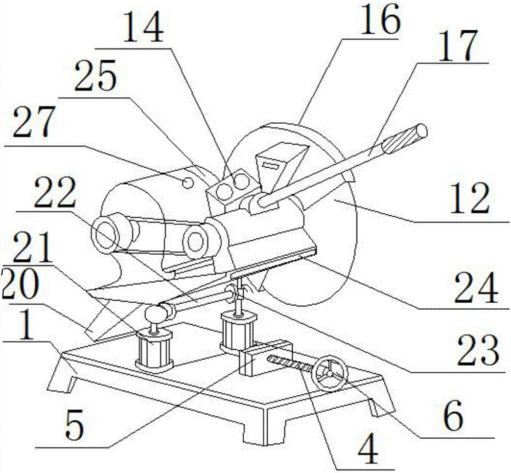
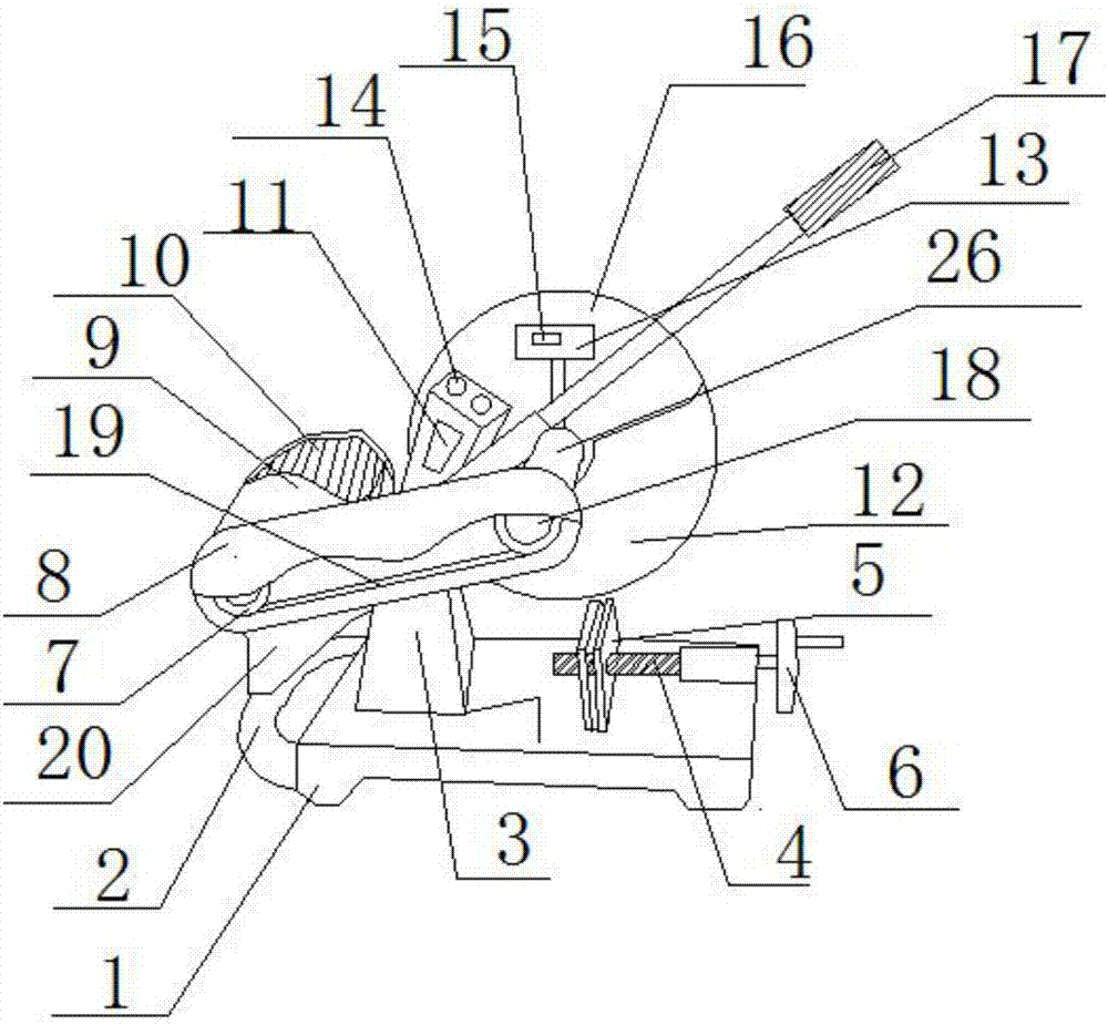
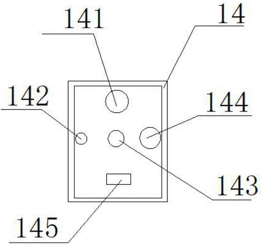
[0023] see Figure 1-3 , the present invention provides a technical solution: a cutting machine device, including a base 1, a tightening block 5 is fixedly connected to the upper surface of the base 1, a screw rod 4 is installed through the tightening block 5, and the end of the screw rod 4 is set away from the tightening block 5 There is a handwheel 6, and the upper surface of the base 1 away from the handwheel 6 is provided with a telescopic cover 3, and the...


PUM


Abstract

The invention discloses a cutting machine device, comprising a base, a tightening block is fixedly connected to the upper surface of the base, a screw rod is arranged through the tightening block, and a hand wheel is arranged at the end of the screw rod far away from the tightening block. A telescopic cover is provided on the upper surface of the base away from the handwheel, the upper end of the telescopic cover is connected to a motor through a support platform, the outer surface of the motor is provided with a motor cover, and the output shaft of the motor is fixedly connected to the second runner. The second runner is rotatably connected to the first runner through a belt, and a belt cover is arranged on the outside of the belt, and a support arm is fixedly connected to the bottom of one end of the belt cover near the second runner, and the first runner is rotatably connected to There is a cutting sheet, and the invention relates to the technical field of cutting machinery. This kind of cutting machine device solves the problem of excessive wear and consumption of the existing cutting machine, and through the setting of the oil tank, oil can be refueled at any time, and the switching of cutting speeds in different gears can be realized through the controller.

Description

technical field [0001] The invention relates to the technical field of cutting machines, in particular to a cutting machine device. Background technique [0002] The existing cutting machine is composed of a cutting unit and a base. The cutting unit includes a handle, a motor and a cutting piece. The motor and the cutting piece are connected by a conveyor belt. The bottom of the cutting unit is fixed with a rotating shaft, and the rotating shaft is mounted on the base. In the two installation holes of the support frame set on the top, there is also a clamp for clamping the material to be cut on the base. When cutting the material, the motor drives the cutting piece to rotate rapidly through the conveyor belt, and the person presses the handle downward to start cutting. materials. However, due to the direct friction between the rotating shaft and the supporting frame, the contact between the rotating shaft and the supporting frame is very worn. At the same time, due to the e...

Claims


Application Information

Patent Timeline
Patent Type & Authority Applications(China)
IPC IPC(8): B23D79/00B23Q1/26B23Q11/10B23Q11/08
CPCB23D79/00B23Q1/26B23Q11/08B23Q11/10
Inventor 邱卿芳
Owner 福州群欣企业管理咨询有限公司
Why Eureka
Try Eureka