Eureka AIR delivers breakthrough ideas for toughest innovation challenges, trusted by R&D personnel around the world.

Fast dismounting and mounting structure of rear housing of electronic device

A technology for electronic equipment and rear casings, which is applied in the field of quick disassembly and assembly of electronic equipment rear casings, and can solve the problems of troublesome installation and disassembly, time-consuming, and high labor costs

Active Publication Date: 2018-04-20
深圳市康冠科技股份有限公司
View PDF4 Cites 4 Cited by
  • Summary
  • Abstract
  • Description
  • Claims
  • Application Information

AI Technical Summary

Problems solved by technology

[0003] There are many existing LCD TV brands and various sizes of TVs, and the corresponding specifications and sizes of TV rear shells are also diverse. Therefore, manufacturers usually use manual work to fasten the TV rear shell. During the assembly process, the TV rear case and the backplane of the TV module need to be fastened together. The fastening method is usually screw connection, and the screw connection is often realized manually or by machine. These repeated locking and screw removal operations will It consumes a lot of labor costs, and the installation and disassembly process is cumbersome and time-consuming

Method used


Image

  • Fast dismounting and mounting structure of rear housing of electronic device
  • Fast dismounting and mounting structure of rear housing of electronic device
  • Fast dismounting and mounting structure of rear housing of electronic device

Examples


Embodiment Construction

[0032] The following will clearly and completely describe the technical solutions in the embodiments of the present invention with reference to the accompanying drawings in the embodiments of the present invention. Obviously, the described embodiments are only some, not all, embodiments of the present invention. Based on the embodiments of the present invention, all other embodiments obtained by persons of ordinary skill in the art without making creative efforts belong to the protection scope of the present invention.

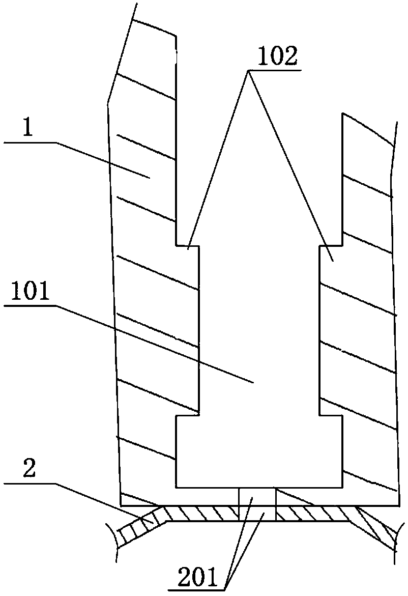
[0033] Please refer to figure 1 , figure 1 It is a structural schematic diagram of a rear shell and a back plate in a specific embodiment provided by the present invention.

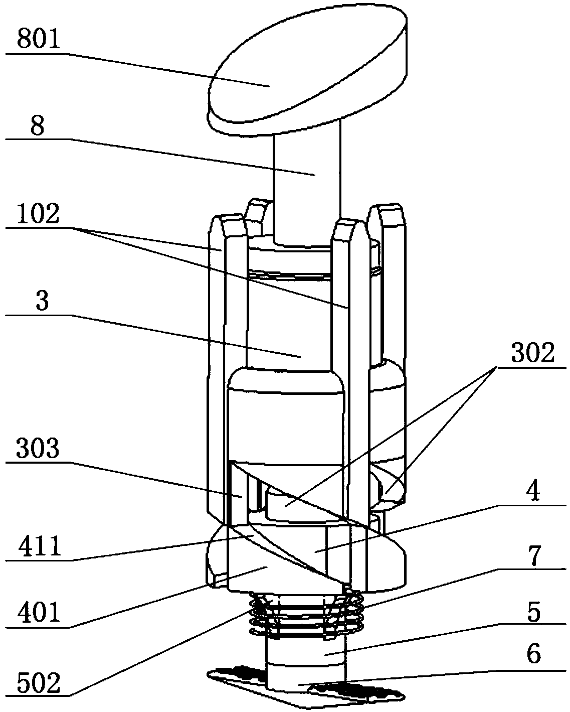
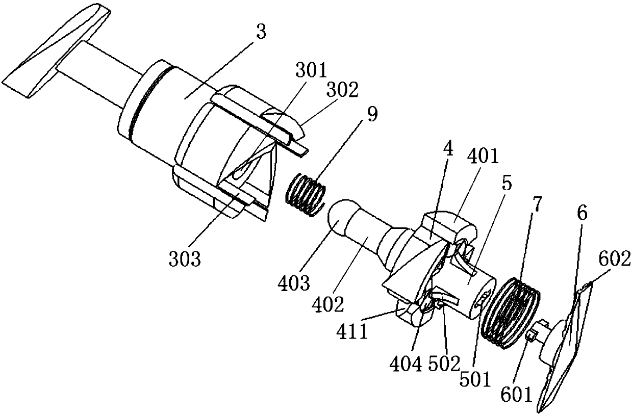
[0034] In a specific embodiment provided by the present invention, the quick disassembly structure of the rear case 1 of the electronic device mainly includes the rear case 1 , the back plate 2 and quick fasteners.

[0035] Wherein, the back plate 2 is closely attached to the inner wall...


PUM


Abstract

The present invention discloses a fast dismounting and mounting structure of a rear housing of an electronic device. The structure comprises a rear housing, a backboard and a fast fastener, and the fast fastener comprises a pressing column, a rotating disk, a clamp connection column and a turn-lock clasp board. When the mounting between the rear housing and the backboard is performed, the pressingcolumn is pressed to allow each wedge-shaped groove at the bottom portion of the pressing column to cooperate with each wedge-shaped block on the rotating disk, the pressing column and the rotating disk are integrated into one body, the rotating dick is rotated to drive the synchronous rotation of the clamp connection column and the turn-lock clasp board to allow the turn-lock clasp board to fasten the bottom surface of the backboard and allow the turn-lock clasp board to be located out of an opening range of a bar-shaped through hole, namely the turn-lock clasp board cannot pass through thebar-shaped through hole, in this process, the amount of compression of a tensioning spring gradually reaches the maximum value, two ends of the tensioning spring are respectively abutted against the surfaces of the rotating disk and the rear housing, and the tensioning spring applies large axial positive pressures to the rotating disk and the rear housing, so that a pressure of the tensioning spring is applied to the surface of the rear housing, the tightening force of the turn-lock clasp board is applied to the bottom surface of the backboard, the stable fixed connection of the rear housing and the backboard is achieved under the act of the two applied forces, and the mounting is installed.

Description

technical field [0001] The invention relates to the technical field of mechanical design, in particular to a quick disassembly and assembly structure for the rear case of an electronic device. Background technique [0002] There are many types of electronic equipment, such as household appliances. Nowadays, many household appliances can be developed to hang on the wall or the surface of other objects in order to avoid occupying the space of the house, such as TVs. Many thin TVs can be directly hung on the wall for use. , not only saves ground space, but also improves the user's audio-visual experience. [0003] There are many existing LCD TV brands and various sizes of TVs, and the corresponding specifications and sizes of TV rear shells are also diverse. Therefore, manufacturers usually use manual work to fasten the TV rear shell. During the assembly process, the TV rear case and the backplane of the TV module need to be fastened together. The fastening method is usually s...

Claims


Application Information

Patent Timeline
Patent Type & Authority Applications(China)
IPC IPC(8): H05K5/02H05K7/14
CPCH05K5/0217H05K7/1438
Inventor 凌斌
Owner 深圳市康冠科技股份有限公司
Why Eureka
Eureka Blog
Learn More