
Water conservancy project water sand content sampling device

A sampling device and water conservancy engineering technology, applied in the direction of sampling devices, etc., can solve the problems of difficult sediment collection, difficulties, and differences in the arrangement of collection points, etc., and achieve the effect of improving sampling effect, low price, and easy promotion

Active Publication Date: 2018-04-20
童航
View PDF16 Cites 4 Cited by
  • Summary
  • Abstract
  • Description
  • Claims
  • Application Information

AI Technical Summary

Problems solved by technology

When the invention collects water samples, it adopts the method of global coverage, and collects all points on the vertical height at the same time. The overall equipment is huge, and there are many pipelines that are difficult to maintain. Due to the different depths of water bodies, the arrangement of collection points is also different. cannot be adjusted;
[0004] Publication number CN105738152A discloses a layered continuous sediment collection device for large deep reservoirs, including a floating platform, a handle device, a pulley assembly, a cable, a suspended sand collection bucket, a suspended sediment collector, a counterweight, and a triangular Fixed support; to solve the problem of difficult maintenance and high cost in the layered observation of sediment suspended matter in large deep reservoirs, and overcome the difficulty of collecting layered sediment suspended matter in large deep reservoirs and the lack of representativeness of single point collection
This invention collects for reservoirs. Within the scope of the reservoir, the fluidity of the water quality is relatively weak, and the suspended sand collection bucket can be fixed by cables. sand collection

Method used


Image

  • Water conservancy project water sand content sampling device
  • Water conservancy project water sand content sampling device

Examples


Embodiment Construction

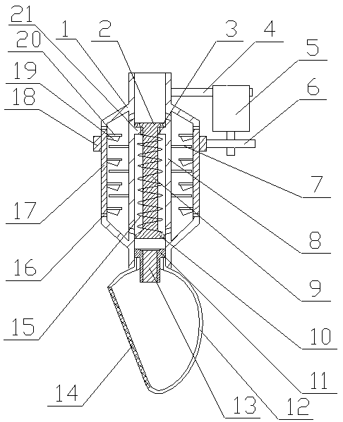
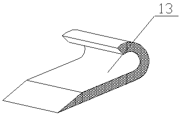
[0025] A water quality and sediment content sampling device for a water conservancy project of the present invention is realized in this way. When in use, when detecting water quality and sediment content, first place the collecting cover (12) in the water body, drive the motor (5) to work, and the motor The shaft drives the transmission gear (6) to rotate, the transmission gear (6) drives the ring gear (18) to rotate, the ring gear (18) drives the outer casing to rotate, and then the outer casing drives a plurality of wheel discs (20) to rotate, and the wheel disc (20) It drives the connected multiple rotating blades (19) to rotate, and a negative pressure is formed in the outer casing to suck water into the collecting cover (12), and the retaining net (14) filters out the sundries in the water, and the inside of the collecting cover (12) The water flows into the fixed casing, and after being filtered by the filter element (13) in the fixed casing, it flows into the inner casi...


PUM


Abstract

The invention relates to a water conservancy project water sand content sampling device, and discloses a sand content sampling device for intercepting sand contained in water and adsorbing the sand through collecting and gathering. The device is characterized in that an annular baffle plate is arranged on an inner sleeve pipe in a sleeving way, and is made of silica gel; an annular steel wire framework is embedded into the silica gel; two ends of an outer sleeve pipe are respectively arranged on the annular baffle plate through pivotal bearings; a plurality of wheel plates are equidistantly arranged on an inner wall of the outer sleeve pipe; a rotary pate is a wave ring; a plurality of rotary blades are arranged on the rotary plate in an equally-angular way, and are parallel to one another; a plurality of guide vanes are equidistantly arranged on an outer wall of the inner sleeve pipe, and are respectively located between every two adjacent wheel plates; four through holes are formed in the inner sleeve pipe, and are respectively communicated with the outer sleeve pipe; the four through holes form two groups, each of which including two through holes; the two groups of through holes are distributed up and down; a limiting ring is arranged on an inner wall of the inner sleeve pipe; a connecting rod is arranged in the inner sleeve pipe; one end of the connecting rod penetrates through the limiting ring so as to be connected with a limiting plate; two water outlet holes are formed in the limiting plate.

Description

technical field [0001] The invention relates to a sampling device for water quality and sand content in water conservancy projects, relating to a device for collecting and sampling water quality sand content in the process of water quality and sand content detection, belonging to the field of water conservancy inspection. In particular, it relates to a sand sampling device which intercepts sand in water quality and absorbs sand by collecting and accumulating. Background technique [0002] At present, in the water conservancy and water quality testing, the sediment content detection of water quality is particularly important, but because the sediment in the natural water quality is mostly suspended sediment, the uniformity is poor, the sediment content is distributed along the vertical direction, and the density The larger sediment is located at the bottom layer. At present, the sediment is collected first, and then the suspended sediment is layered and separated to measure t...

Claims


Application Information

Patent Timeline
IPC IPC(8): G01N1/14
CPCG01N1/14
Inventor 不公告发明人
Owner 童航
Learn More