
Bridge cover girder construction supporting device

A supporting device and cover beam technology, which is applied in bridges, bridge construction, erection/assembly of bridges, etc., can solve problems such as difficult dismantling and difficult height adjustment of sandboxes, and achieve low production costs, avoid unsafe factors, and reduce heights Effect

Pending Publication Date: 2018-04-20
CCFED THE FIGTH CONSTR & ENG
View PDF6 Cites 1 Cited by
  • Summary
  • Abstract
  • Description
  • Claims
  • Application Information

AI Technical Summary

Problems solved by technology

[0002] In the construction of bridge engineering, the most common method of piercing steel rods and hoops in the construction of cover (system) beams is the most common method. In traditional construction techniques, jacks and sandboxes are often used as supports. There are relatively large unsafe factors in the use of jacks. However, it is difficult to adjust the height of the sandbox during use and it is not easy to remove it. Therefore, we propose

Method used


Image

  • Bridge cover girder construction supporting device
  • Bridge cover girder construction supporting device

Examples


Embodiment Construction

[0015] The following will clearly and completely describe the technical solutions in the embodiments of the present invention with reference to the accompanying drawings in the embodiments of the present invention. Obviously, the described embodiments are only some, not all, embodiments of the present invention.

[0016] In describing the present invention, it should be understood that the terms "upper", "lower", "front", "rear", "left", "right", "top", "bottom", "inner", " The orientation or positional relationship indicated by "outside", etc. is based on the orientation or positional relationship shown in the drawings, and is only for the convenience of describing the present invention and simplifying the description, rather than indicating or implying that the referred device or element must have a specific orientation, so as to Specific orientation configurations and operations, therefore, are not to be construed as limitations on the invention.

[0017] refer to Figure ...


PUM


Abstract

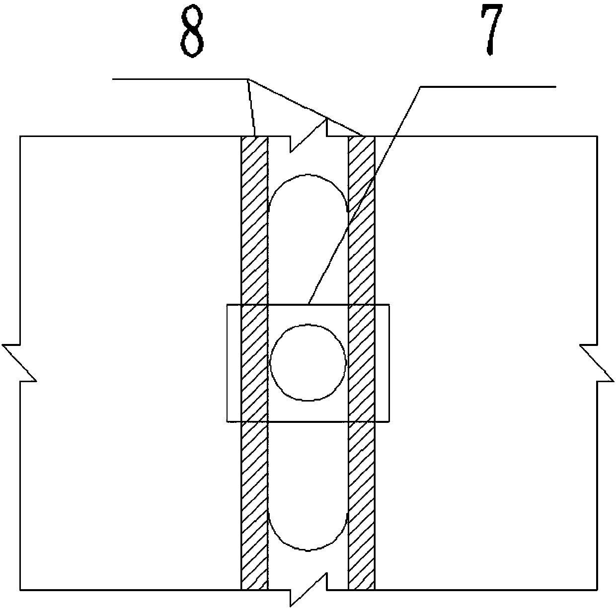
The invention discloses a bridge cover girder construction supporting device. The device comprises an iron box, a large through hole is formed in the middle of the iron box, a threaded hole communicated with the exterior of the iron box is formed in the side wall of one side of the large through hole, and the threaded hole is internally in threaded connection with a bolt; the upper side wall of the iron box is provided with a lower iron wedge, the upper end of the lower iron wedge is provided with an upper iron wedge, mounting holes are formed in the lower iron wedge and the upper iron wedge and internally connected with an opposite pulling rod, the two ends, located outside the mounting holes, of the opposite pulling rod are both provided with nuts, the two sides of the exterior of each mounting hole are provided with stiffened steel plates, and the stiffened steel plates are assembled in the inner side walls of the lower iron wedge and the upper iron wedge. The bridge cover girder construction supporting device is simple in structure, easy to operate, scientific and reasonable in design, short in production cycle, low in production cost and capable of being used for a long time after one-time manufacturing, no amortization occurs after turnover is conducted multiple times, and not only are unsafe factors of a jack avoided, but also the device can be easily adjusted and dismantled and meet production and safety requirements.

Description

technical field [0001] The invention relates to the technical field of building formwork support structures, in particular to a construction support device for bridge cap beams. Background technique [0002] In the construction of bridge engineering, the most common method of piercing steel rods and hoops in the construction of cover (system) beams is the most common method. In traditional construction techniques, jacks and sandboxes are often used as supports. There are relatively large unsafe factors in the use of jacks. However, it is difficult to adjust the height of the sandbox during use and it is not easy to disassemble. For this reason, we propose. Contents of the invention [0003] The purpose of the present invention is to solve the problems in the background technology, and propose a bridge cap beam construction support device. [0004] In order to achieve the above object, the present invention adopts the following technical solutions: [0005] A bridge cover...

Claims


Application Information

Patent Timeline
Patent Type & Authority Applications(China)
IPC IPC(8): E01D21/00
CPCE01D21/00
Inventor 刘烨张嵩贺翔王祥雷杨李帆
Owner CCFED THE FIGTH CONSTR & ENG
Learn More