
Supporting frame paint spaying device

A support frame and mounting frame technology, applied in the direction of spraying devices, spray booths, etc., can solve the problems of incomplete painting on the surface of the paint, low painting efficiency, and waste of paint in the environment, and achieve uniform and high-quality spray paint, fast spray paint atomization, and structure compact design effect

Inactive Publication Date: 2018-04-20
长沙双合盛企业管理有限公司
View PDF6 Cites 3 Cited by
  • Summary
  • Abstract
  • Description
  • Claims
  • Application Information

AI Technical Summary

Problems solved by technology

[0002] Spraying refers to a method in which a spray gun is dispersed into uniform and fine mist droplets by means of air pressure and applied to the surface of the object to be coated (it can be divided into air spraying, airless spraying and electrostatic spraying, etc. spraying method), pressurized spraying is often used in construction machinery manufacturing, because the current spraying device adopts an open structure, and the spraying efficiency is low, resulting in various problems in actual use
[0003] In order to solve the above problems, the present invention is proposed, which overcomes the current open paint spraying device, because the paint atomization is easily affected by the external air convection, which causes the waste of paint and the pollution of the environment, and destroys the uniform drop of the evenly atomized paint The process makes the paint surface spraying incomplete, so that the present invention has the advantages of compact structure design, fast and sufficient spray paint atomization, good protection effect of partition operation, green environmental protection, uniform spray paint and high quality.

Method used


Image

  • Supporting frame paint spaying device
  • Supporting frame paint spaying device
  • Supporting frame paint spaying device

Examples


Embodiment Construction

[0018] The technical solutions in the embodiments of the present invention will be clearly and completely described below in conjunction with the accompanying drawings in the embodiments of the present invention. Obviously, the described embodiments are only a part of the embodiments of the present invention, rather than all the embodiments. Based on the embodiments of the present invention, all other embodiments obtained by those of ordinary skill in the art without creative work shall fall within the protection scope of the present invention.

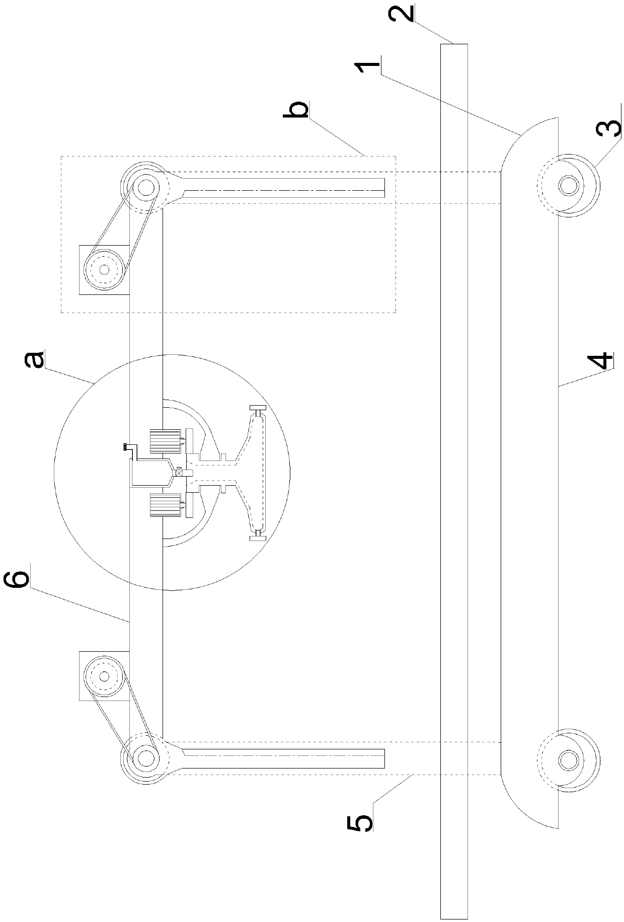
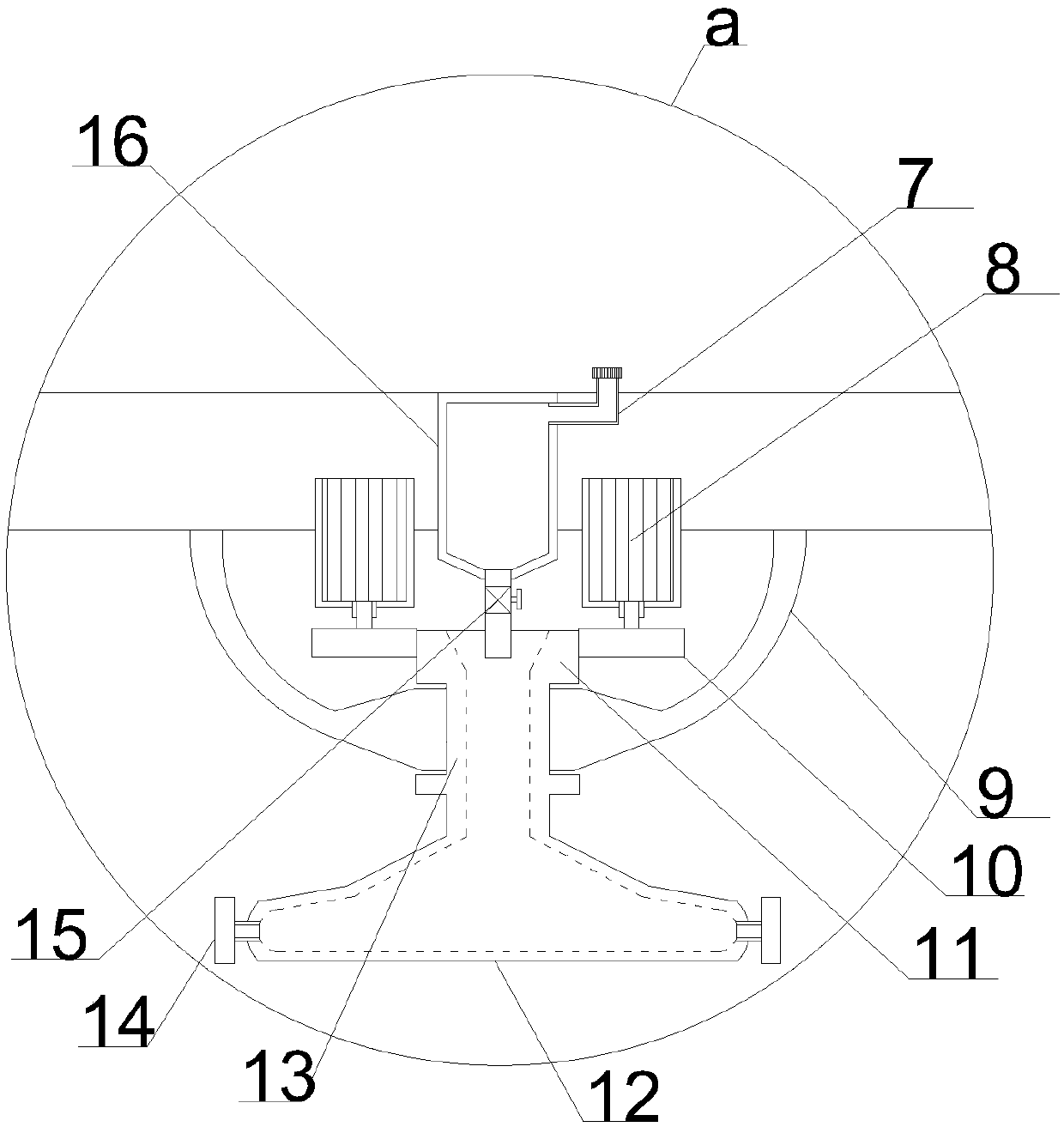
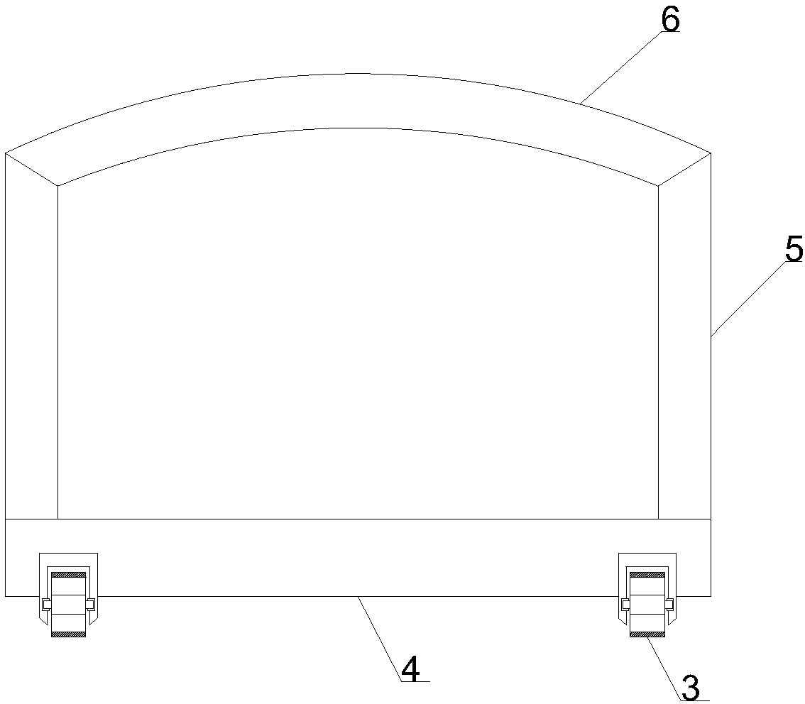
[0019] See Figure 1~4 In an embodiment of the present invention, a painting device for a support frame includes a support mounting plate 4, the lower end of the support mounting plate 4 is symmetrically semi-inlaid with support moving wheels 3, and the upper end of the support mounting plate 4 has four vertical corners. The support mounting column 5 is set upwards, the front and rear support mounting columns 5 on the same side are conne...


PUM


Abstract

The invention discloses a supporting frame paint spaying device comprising a supporting mounting plate. Supporting mounting columns are vertically and upwards arranged at the four corners of the upperend of the supporting mounting plate, partition plates are connected between the supporting mounting columns on the front side as well as the between the supporting mounting columns on the rear side,and a supporting mounting frame is horizontally arranged at the upper ends of the supporting mounting columns. Rotating partitioning structures comprise rotating mounting cylinders arranged at the left end and the right end of the supporting mounting frame, matched with the supporting mounting columns on the front side and the right side and coaxially embedded through rotary shafts, rotating partitioning plates are arranged at the lower ends of rotating mounting cylinders and matched with the supporting mounting columns on the front side and the rear side, the front sides of the rotating mounting cylinders are coaxially provided with transmission belt wheels through the rotary shafts extending out of the supporting mounting frames, and driving motors are symmetrically arranged at the leftend and the right end of the supporting mounting frame. The supporting frame paint spaying device has the advantages that the structural design is compact, paint spraying atomization is rapid and sufficient, the partitioning operation protection effect is good, environmental friendliness is achieved, and paint spraying is even, and the quality is high.

Description

Technical field [0001] The invention relates to a building frame manufacturing equipment, in particular to a spray painting device for a support frame. Background technique [0002] Paint spraying refers to a method in which spray guns are used to disperse into uniform and fine mist droplets by means of air pressure and applied to the surface of the object to be coated (can be divided into air spray paint, airless spray paint and electrostatic spray paint, etc. Spray painting method), pressurized spray painting is often used in construction machinery manufacturing. Because the currently used paint spraying device adopts an open structure and the painting efficiency is low, various problems occur in actual use. [0003] In order to solve the above-mentioned problems, the present invention is proposed, which overcomes the open paint spraying device currently in use. Because the atomization of paint is very susceptible to the influence of external air convection, it causes waste of pa...

Claims


Application Information

Patent Timeline
Patent Type & Authority Applications(China)
IPC IPC(8): B05B16/80B05B15/80B05B13/04B05B15/62B05B14/44
CPCB05B13/0421
Inventor 陆江斌
Owner 长沙双合盛企业管理有限公司
Learn More