
Novel short-circuit structure of test connection terminals of secondary equipment

A technology of secondary equipment and connecting terminals, applied in the direction of fixed/insulated contact members, connections, contact parts, etc., can solve problems such as incorrect action, small electrical distance, poor short-circuit, etc., to prevent disconnection or virtual connection, Improve efficiency and ensure safety

Active Publication Date: 2018-04-17
HUZHOU ELECTRIC POWER SUPPLY CO OF STATE GRID ZHEJIANG ELECTRIC POWER CO LTD +1
View PDF3 Cites 1 Cited by
  • Summary
  • Abstract
  • Description
  • Claims
  • Application Information

AI Technical Summary

Problems solved by technology

[0004] The deficiencies of this application are: 1. The metal parts of the connecting piece and the shorting piece are exposed, and the electrical distance is small. When working with the same power supply and different power supply cores, it is easy to cause accidental contact, discharge, etc., resulting in insufficient protection. Correct action; 2. The connecting piece and the shorting piece are fixed by multiple screws, and it is easy to have different tightening degrees of the fixing screws, resulting in poor short-circuiting of individual points and affecting the output of the secondary voltage (missing item); 3. Short-circuiting The chip is pure metal, short circuit operation is not safe
[0005] In order to improve the short-circuit efficiency of the secondary equipment voltage test connection terminal and reduce the occurrence of secondary circuit disconnection or virtual connection caused by the traditional short-connection method, a new type of secondary equipment test connection terminal with convenient and reliable connection is designed. A short-circuit structure is necessary

Method used


Image

  • Novel short-circuit structure of test connection terminals of secondary equipment
  • Novel short-circuit structure of test connection terminals of secondary equipment

Examples


Embodiment Construction

[0024] The present invention will be further described below in conjunction with the accompanying drawings and specific embodiments.

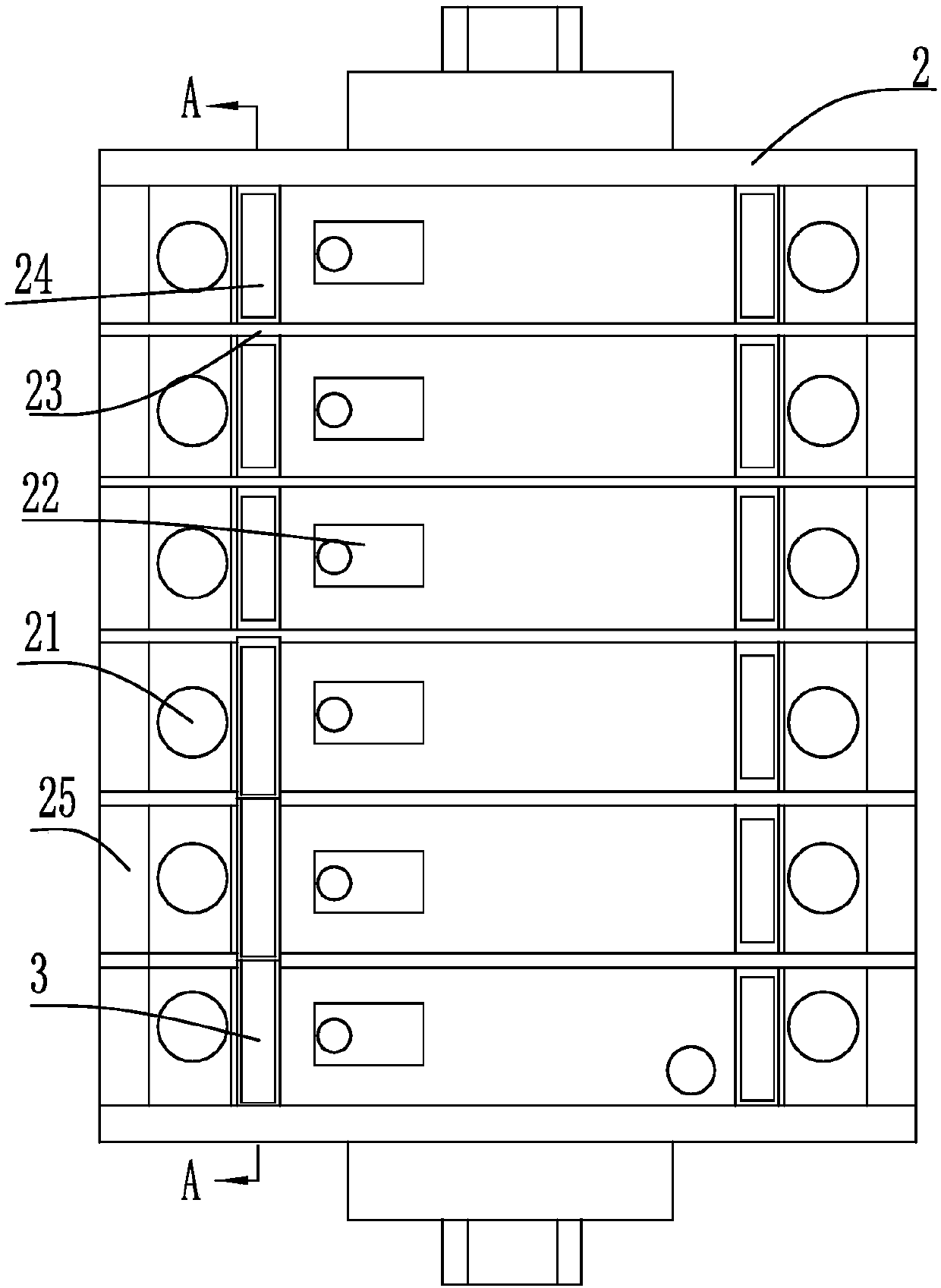
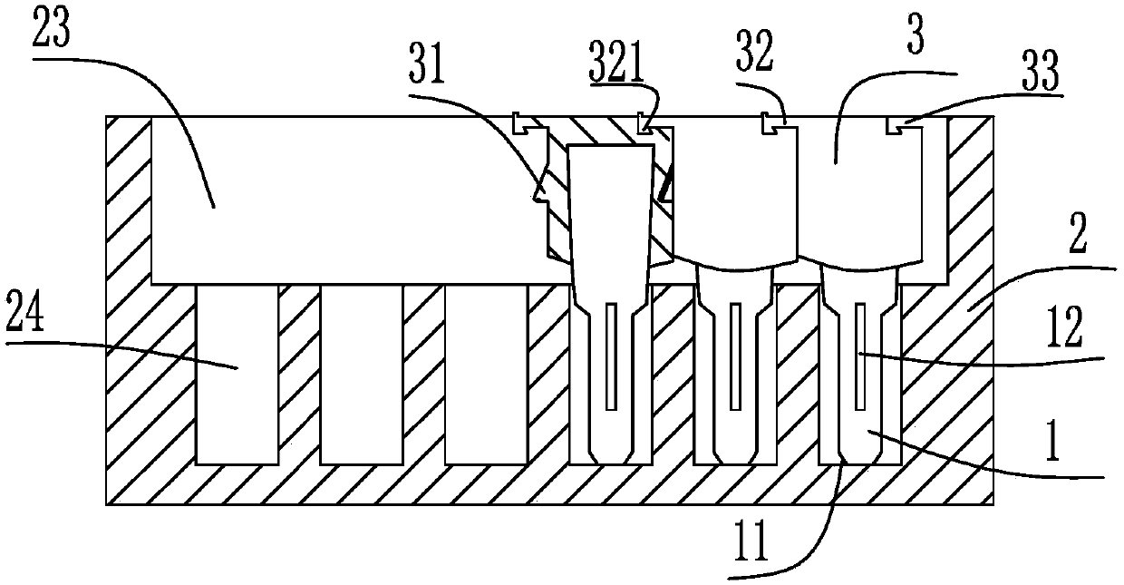
[0025] figure 1 with figure 2 Among them, a new type of secondary equipment test connection terminal shorting structure, including a long and thick shorting pin 1 and a terminal row 22 that can accommodate the shorting pin 1; the upper side of the shorting pin 1 is designed There is an insulating sleeve 3; the two sides of the shorting pin 1 are respectively provided with guide grooves 12, and the guiding grooves 12 are parallel to the length direction of the shorting pin 1. The guiding groove 12 is arranged at the middle position of the shorting pin 1 . The lower side of the short-circuit pin 1 is provided with a transition arc surface 11 which is convenient for inserting the short-circuit pin 1 . The terminal block 22 includes terminals 21 arranged symmetrically on both sides of the terminal block 22. The inside of the terminal 21 is prov...


PUM


Abstract

The invention discloses a novel short-circuit structure of test connection terminals of secondary equipment. The structure comprises bar-shaped short-circuit pins in certain thickness and a terminal row capable of accommodating the short-circuit pins, insulation sleeves are arranged on the short-circuit pins respectively, the two sides of each short-circuit pin are provided with guiding grooves respectively, and the guiding grooves are in parallel with the length direction of the short-circuit pin. The short-circuit structure has the advantages that a plug-in type short-circuit manner is usednewly, and the short-circuit efficiency is improved; the short-circuit pins have a stronger damping effect after being plugged into the terminal row, during use, the short-circuit pins are pressed into the terminal row, it is ensured that the pins are plugged in place, and a secondary loop is prevented from break or false connection; and the tail portions of the short-circuit pins are provided with the insulation sleeves additionally, and the safety of short-circuit operation is ensured.

Description

technical field [0001] The invention relates to the technical field of tool devices for electric power engineering, in particular to a novel secondary equipment test connection terminal short-circuit structure. Background technique [0002] The secondary equipment test connection terminals are widely used behind the secondary compartment of the switchgear and the protective screen cabinet. They are used as connectors to supply various secondary currents and voltages to various protective devices, or to supply currents and voltages output by various protective devices. The voltage is transferred to the terminal block, and then output to other interval protection devices with the secondary cable. Some test terminals, such as current and voltage loops, need to be placed with shorting strips, which can be opened or removed when in use, and no shorting is used; some signals share the positive power supply, and the configuration of power lines can be reduced by using shorting stri...

Claims


Application Information

Patent Timeline
Patent Type & Authority Applications(China)
IPC IPC(8): H01R31/08H01R13/02H01R13/40
CPCH01R13/02H01R13/40H01R31/08
Inventor 刘莹孔晓昀张刚黄志华刘扬谢英男刘智涯钱伟隆陈利恒许伟
Owner HUZHOU ELECTRIC POWER SUPPLY CO OF STATE GRID ZHEJIANG ELECTRIC POWER CO LTD
Learn More