Eureka AIR delivers breakthrough ideas for toughest innovation challenges, trusted by R&D personnel around the world.

Linear motor primary part with isolation cooling structure

A linear motor, cooling structure technology, applied in electrical components, electric components, cooling/ventilation devices, etc., can solve the problems of low refrigerant use efficiency, increased production costs, cooling pipeline breakdown, etc., to reduce the risk of damage and save money Production cost, effect of reducing heat dissipation cost

Pending Publication Date: 2018-04-13
GUANGZHOU HAOZHI ELECTROMECHANICAL
View PDF7 Cites 5 Cited by
  • Summary
  • Abstract
  • Description
  • Claims
  • Application Information

AI Technical Summary

Problems solved by technology

[0004] (1) Adding a large flow of refrigerant has higher requirements on the external cooling pump, and a larger refrigerant pressure and flow rate must be provided. The efficiency of refrigerant use is low, and the requirements for the sealing pressure of the motor are higher; the cooling pipe is close to the coil and there is a risk of breakdown , increasing the difficulty of motor assembly and debugging
[0005] (2) Only using the cooling pipe to simply surround the primary and the machine cannot prevent the machine from absorbing heat well, and the heat insulation effect is not ideal; the additional device isolating the primary from the machine requires additional parts and additional occupation Machine space and cooling flow, increasing production costs

Method used


Image

  • Linear motor primary part with isolation cooling structure
  • Linear motor primary part with isolation cooling structure
  • Linear motor primary part with isolation cooling structure

Examples


Embodiment Construction

[0029] Below, the present invention will be further described in conjunction with the accompanying drawings and specific implementation methods. It should be noted that, under the premise of not conflicting, the various embodiments described below or the technical features can be combined arbitrarily to form new embodiments. .

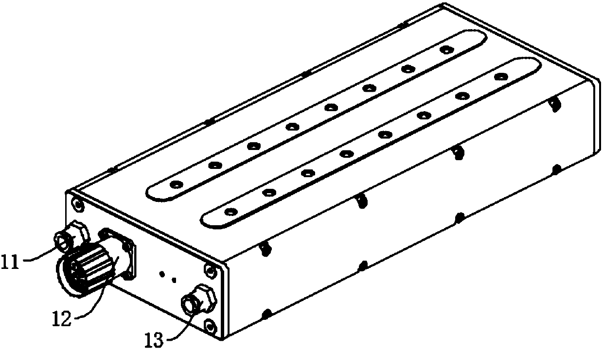
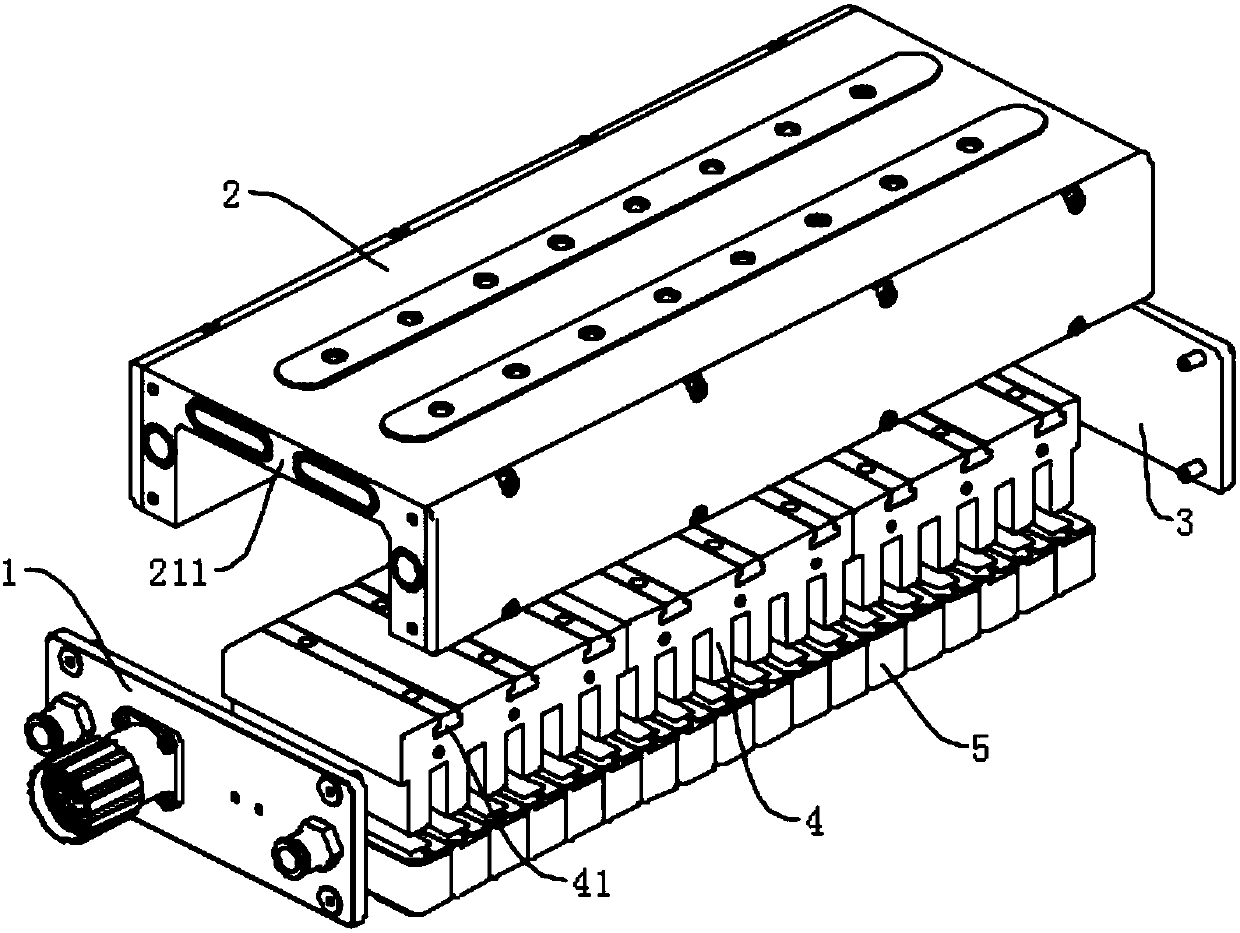
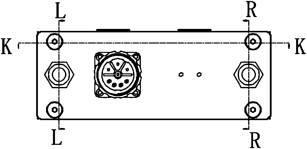
[0030] Figure 1-5 As shown, the primary part of a linear motor with an isolated cooling structure provided by the present invention includes a front end cover 1, a body body 21, an iron core 4, a winding 5, and a cooling water inlet joint 11 and a cooling water outlet provided on the front end cover 1. Connector 13, one side of the body body 21 is provided with a first cooling chamber 24, and the first cooling chamber 24 communicates with the cooling water inlet joint 11, the body body 21 has a back plate 211, and a first through hole is arranged in the back plate 211 212, the first cooling cavity 24 communicates with the cooling water outlet joint 1...


PUM


Abstract

The invention discloses a linear motor primary part with an isolation cooling structure. The linear motor primary part comprises a machine body, an iron core, a winding, a front end cover, a cooling water inlet connector and a cooling water outlet connector, wherein the cooling water inlet connector and the cooling water outlet connector are arranged on the front end cover, a first cooling cavityis formed in one side of the machine body and communicates with the cooling water inlet connector, the machine body is provided with a back panel, a penetrating hole is formed in the back panel, the first cooling cavity communicates with the cooling water outlet connector via the penetrating hole, a plurality of first flow holes and a first waist-shaped hole are formed in the first cooling cavity,the first waist-shaped hole is near to an upper end of the first cooling cavity, a first cooling groove is formed in a part below the first cooling cavity, the first cooling groove communicates withthe first flow holes via the first cooling cavity, the first cooling cavity communicates with the first waist-shaped hole via the penetrating hole, and the first flow holes are lower than the first waist-shaped holes. A cooling structure is additionally arranged in a machine body under the condition that no extra device is additionally arranged, cooling pipeline layout is optimized, and the cooling effect is improved.

Description

technical field [0001] The invention relates to the field of linear motors, in particular to a primary component of a linear motor with an isolated cooling structure. Background technique [0002] At present, linear motors are more and more widely used in industrial machinery. As a direct drive method, compared with traditional servo motor acceleration and deceleration systems and ball screw drive feed systems, linear motors have no intermediate transmission mechanism, making Linear motors have faster speed, acceleration and dynamic response. In addition, the user can flexibly connect the linear motors in series or parallel according to the needs of the use, and change the stroke of the linear motor by changing the combined length of the secondary components (magnetic plates), so as to meet the general large and medium stroke applications. . Since the linear motor will generate a lot of heat during the working process, it is necessary to solve the problem of heat dissipati...

Claims


Application Information

Patent Timeline
Patent Type & Authority Applications(China)
IPC IPC(8): H02K5/20H02K9/19H02K41/02
CPCH02K5/20H02K9/19H02K41/02
Inventor 侯宗毅钟添明郭治汤秀清
Owner GUANGZHOU HAOZHI ELECTROMECHANICAL
Why Eureka
Eureka Blog
Learn More