
Heat dissipating device for electric power equipment box

A technology for power equipment boxes and heat sinks, applied in the cooling/ventilation of substations/switchgears, details of substation/switch layouts, electrical components, etc. , to overcome the unstable connection, improve the service life, and ensure the effect of internal temperature

Inactive Publication Date: 2018-04-13
CHENGDU ZHIQI TECH
View PDF1 Cites 1 Cited by
  • Summary
  • Abstract
  • Description
  • Claims
  • Application Information

AI Technical Summary

Problems solved by technology

[0002] At present, due to many advantages such as small size, low cost and short construction period, box-type power equipment is gradually favored by power companies, and most of them will be used in transformers. Because transformers emit a lot of heat during work, and the equipment box The internal space of the body is narrow, which will cause the temperature in the equipment box to rise sharply, the equipment will easily age and even cause an explosion, which will bring great hidden dangers to residents' life and personal safety. Therefore, there is an urgent need for a high degree of automation, simple operation and The heat dissipation device with good heat dissipation effect, in the prior art, for example, the invention patent with application number 201520322788.8 includes a motor installed in the left box wall of the box body, a cooling fan installed at the output end of the motor and inside the box body, and a cover set The fan cover outside the cooling fan, the controller installed inside the box, the temperature sensor installed on the front side of the box, the bottom plate fixed on the bottom inside the box, the left water chamber and the right side on the left side of the bottom plate The right water chamber is fixed on the serpentine water pipe between the left water chamber and the right water chamber, and several heat sinks are fixed on the bottom plate and located between the adjacent straight pipes of the serpentine water pipe, and are set at the air outlet on the right side of the box body. One end of the serpentine water pipe is connected to the water inlet of the left water chamber, and the other end is connected to the water outlet of the right water chamber, and the water inlet and the water outlet are equipped with electric control switches, motors, temperature sensors and electric control The switches are all connected with the controller. Although the invention is simple in structure, there are many deficiencies and defects. In the existing equipment, the design of the cooling fan has defects, the connection between the cooling fan and the fan cover and the casing is unstable, and the cooling fan It is inconvenient to disassemble. In view of these situations, in order to avoid the above-mentioned technical problems, it is necessary to provide a heat sink for power equipment boxes to overcome the defects in the prior art

Method used


Image

  • Heat dissipating device for electric power equipment box
  • Heat dissipating device for electric power equipment box
  • Heat dissipating device for electric power equipment box

Examples


Embodiment Construction

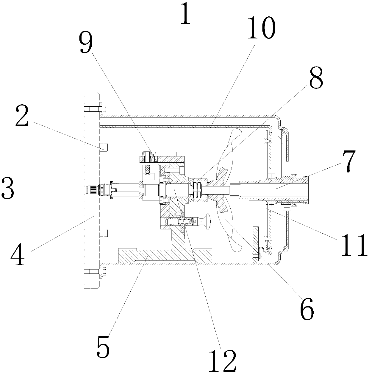
[0015] The following will clearly and completely describe the technical solutions in the embodiments of the present invention with reference to the accompanying drawings in the embodiments of the present invention. Obviously, the described embodiments are only some, not all, embodiments of the present invention. Based on the embodiments of the present invention, all other embodiments obtained by persons of ordinary skill in the art without making creative efforts belong to the protection scope of the present invention.

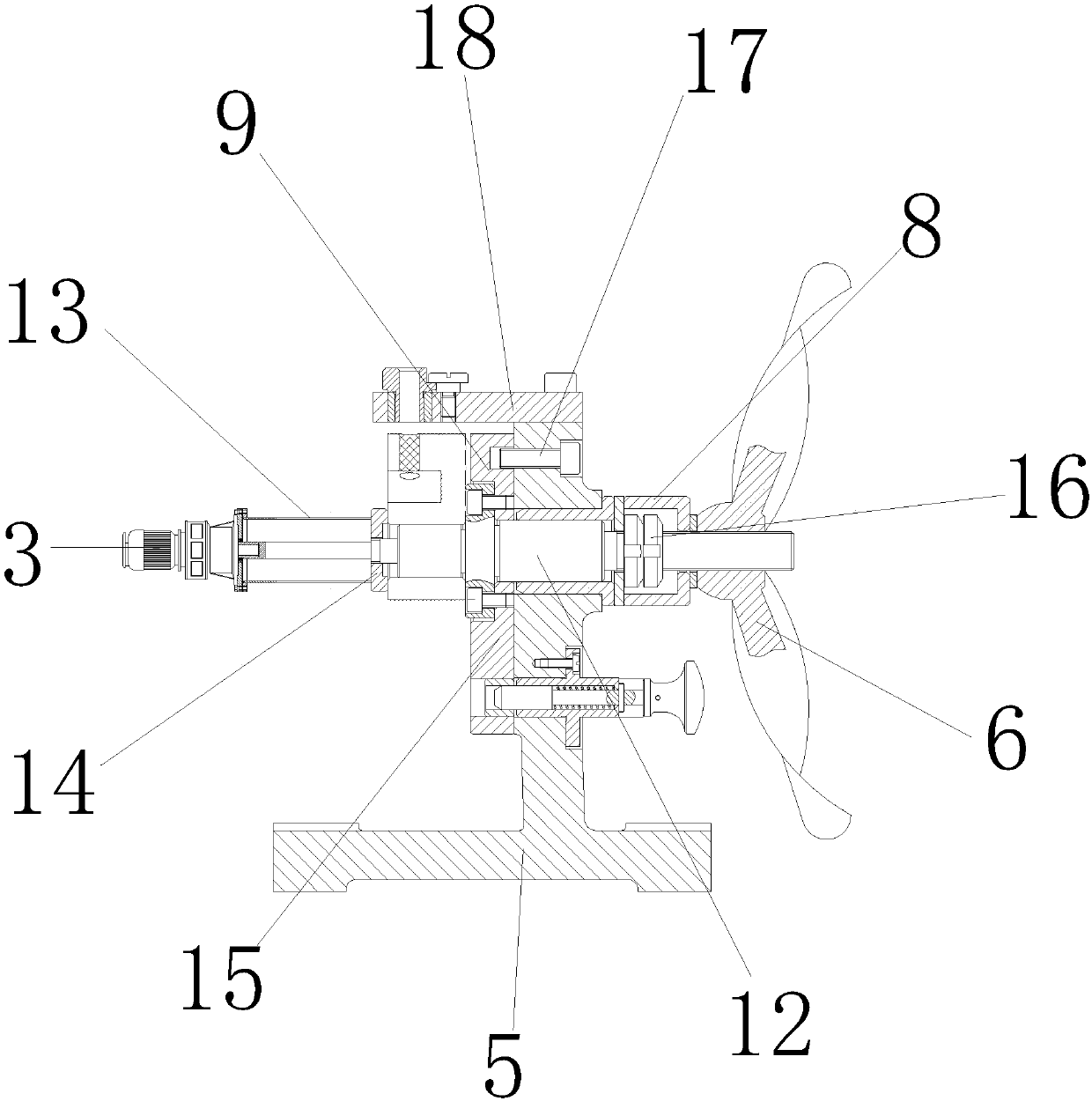
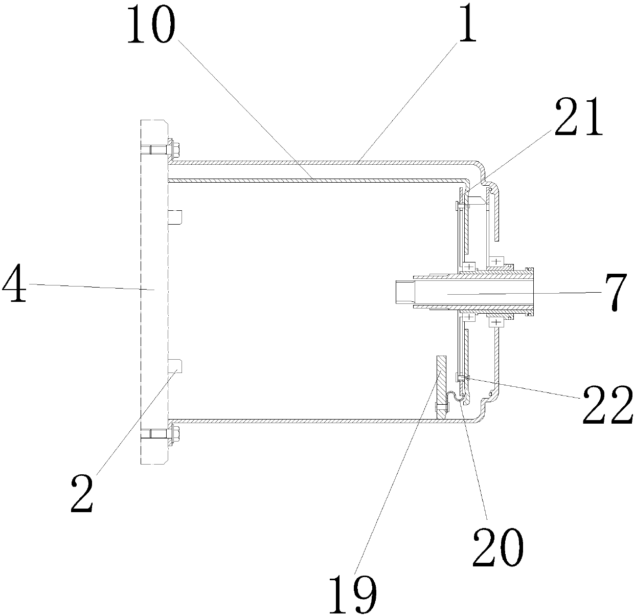
[0016] see Figure 1-4, the present invention provides a technical solution: a heat dissipation device for a power equipment box, including a shield 1, the shield 1 is made of stainless steel, and is used to protect the motor 3 and the fan 6, and the left outer wall of the shield 1 is provided with The base 4, the base 4 is made of stainless steel, and is used to install the motor 3 and the fan 6. The outer wall on the right side of the bottom plate 4 is provi...


PUM


Abstract

The invention discloses a cooling device for a power equipment box, which comprises a shield, the left outer wall of the shield is provided with a base, the right outer wall of the base is connected with the left outer wall of the shield, and the inner wall of the bottom plate A motor is provided, the outer wall of the motor is connected to the inner wall of the bottom plate, a base is installed on the upper surface of the inner wall of the shield, a rotating shaft is sleeved on the inner wall of the base, and the outer wall of the rotating shaft is overlapped with the inner wall of the base. The cooling device for the power equipment box, through the cooperation between the bottom plate, the pad and the shield, under the action of the base, the shield can be quickly opened and closed, and the internal motor and fan can be repaired and maintained. The connection between the top plate and the baffle is more firm, thus overcoming the shortcomings of the traditional power equipment box cooling device, the cooling fan and the fan cover and the box body are not stable, and the cooling fan is inconvenient to disassemble, and the service life of the power equipment is improved. Suitable for promoting applications.

Description

technical field [0001] The invention relates to the technical field of electrical machinery, in particular to a cooling device for an electrical equipment box. Background technique [0002] At present, due to many advantages such as small size, low cost and short construction period, box-type power equipment is gradually favored by power companies, and most of them will be used in transformers. Because transformers emit a lot of heat during work, and the equipment box The internal space of the body is narrow, which will cause the temperature in the equipment box to rise sharply, the equipment will easily age and even cause an explosion, which will bring great hidden dangers to residents' life and personal safety. Therefore, there is an urgent need for a high degree of automation, simple operation and The heat dissipation device with good heat dissipation effect, in the prior art, for example, the invention patent with application number 201520322788.8 includes a motor instal...

Claims


Application Information

Patent Timeline
Patent Type & Authority Applications(China)
IPC IPC(8): H02B1/56H02B1/46
CPCH02B1/565H02B1/46
Inventor 任苗
Owner CHENGDU ZHIQI TECH
Learn More