
Driving method for touch display device

A driving method and a touch display technology, applied to static indicators, data processing input/output process, instruments, etc., can solve the problem of not being able to obtain position information, achieve the effect of improving display quality and preventing excessive load

Active Publication Date: 2018-11-30
CHIPONE TECH BEIJINGCO LTD
View PDF4 Cites 0 Cited by
  • Summary
  • Abstract
  • Description
  • Claims
  • Application Information

AI Technical Summary

Problems solved by technology

At the end of each display interval, the sensing line corresponding to the last gate line scanned is affected by the last gate line, thus generating noise in the touch detection signal, resulting in the inability to obtain accurate position information for touch detection

Method used


Image

  • Driving method for touch display device
  • Driving method for touch display device
  • Driving method for touch display device

Examples


Embodiment Construction

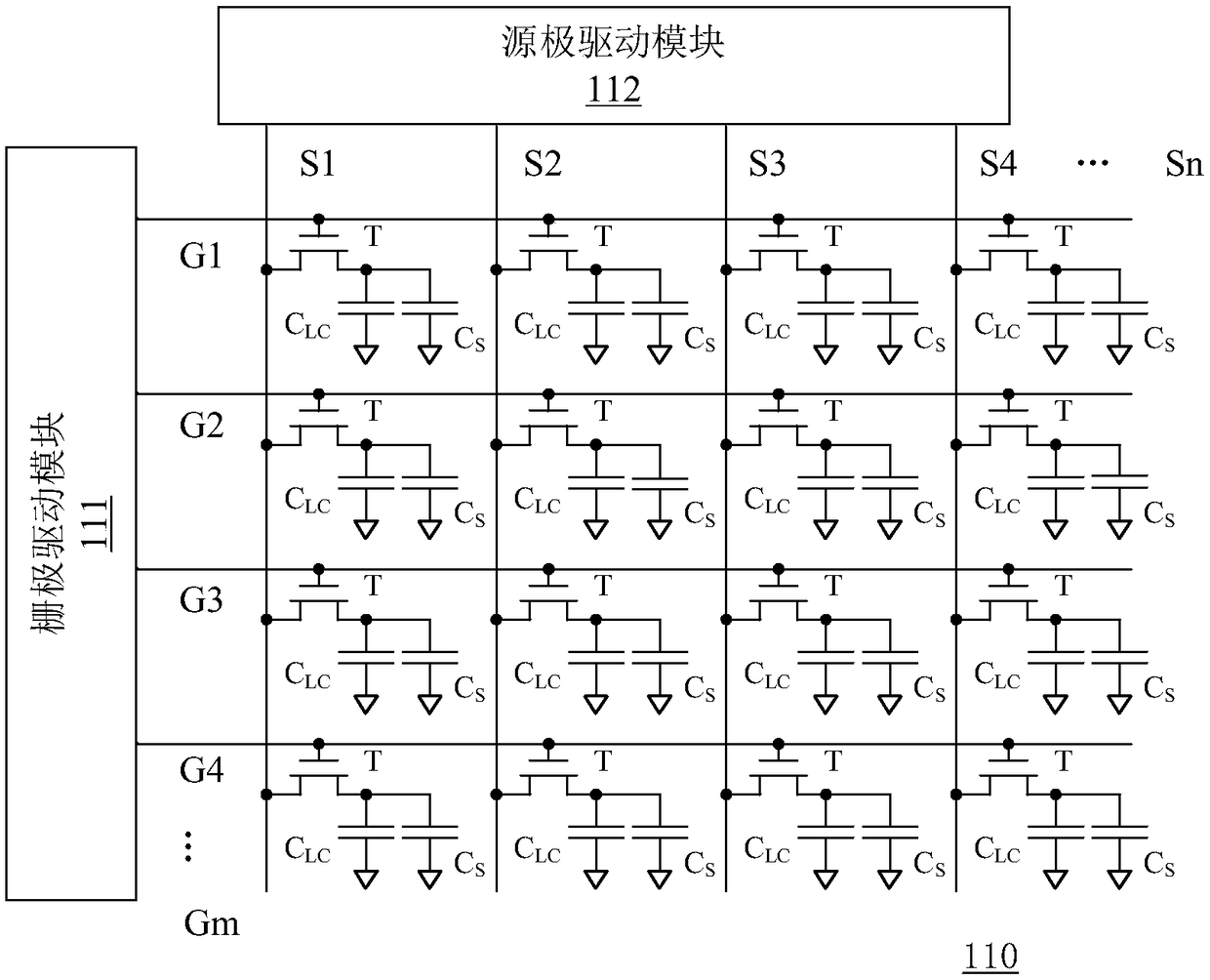
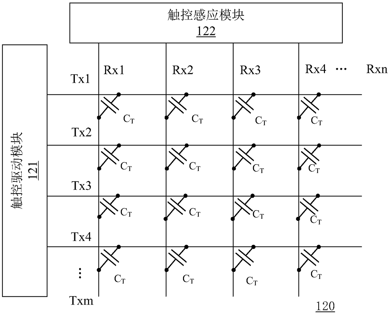
[0029] Hereinafter, the present invention will be described in more detail with reference to the accompanying drawings. In the various figures, identical elements are indicated with similar reference numerals. For the sake of clarity, various parts in the drawings have not been drawn to scale. Also, some well-known parts may not be shown in the drawings.

[0030] In the following, many specific details of the present invention are described, such as device structures, materials, dimensions, processing techniques and techniques, for a clearer understanding of the present invention. However, the invention may be practiced without these specific details, as will be understood by those skilled in the art.

[0031]In the present application, the term "subframe" represents a unified time unit in the control process of the touch display device. For the display part, "subframe" means a time period for displaying a complete image on the display screen, and "display interval" means a...


PUM


Abstract

The invention discloses a driving method used for a touch display apparatus. The method comprises the steps of setting frame cycles of multiple sub-frames; dividing each sub-frame into q display intervals and multiple touch intervals; scanning a predetermined quantity of gate lines in each display interval; driving a predetermined quantity of driving lines in each touch interval, and obtaining induction signals on multiple induction lines to obtain touch information data; selecting the first sub-frame in each frame cycle or continuous frame cycles as a reference sub-frame; in each touch interval of the reference sub-frame, detecting noise values of the induction signals on the corresponding induction lines; and in each frame cycle or the continuous frame cycles, compensating the touch information data corresponding to the sub-frames expect the reference sub-frame in the frame cycle or the continuous frame cycles according to the noise values obtained in the reference sub-frame period.According to the method, the signal-noise ratios of the induction signals can be increased by adopting the compensation method while the display quality is improved in a line shift way.

Description

technical field [0001] The present invention relates to the technical field of touch display, and more particularly, to a driving method for a touch display device. Background technique [0002] A capacitive touch display device includes touch electrodes integrated in a display screen and a driving circuit thereof. The touch electrodes are composed of patterned single or multiple metal layers, which can cover the display panel or be embedded in the display panel, for example, on the array substrate of the display panel. [0003] The touch display device has both a display driving function and a touch driving function. In order to realize image display, the display driving module respectively selects the thin film transistors of the corresponding row of pixel units via a plurality of gate lines in the image frame period. In order to realize touch detection, the touch driving module detects the change of the capacitance value through a plurality of sensing lines (ie, RX line...

Claims


Application Information

Patent Timeline
Patent Type & Authority Patents(China)
IPC IPC(8): G06F3/041G09G3/36
CPCG06F3/0412G06F3/0416G09G3/36
Inventor 冯鹏婓
Owner CHIPONE TECH BEIJINGCO LTD
Learn More