
Clamping device and clamping system

A clamping device and clamping piece technology, which is applied to workpiece clamping devices, manufacturing tools, etc., can solve the problems of many clamping devices and rising costs, and achieve the effects of smooth position, low cost and wide application scenarios.

Pending Publication Date: 2018-04-13
杭州联堤智能科技有限公司
View PDF0 Cites 3 Cited by
  • Summary
  • Abstract
  • Description
  • Claims
  • Application Information

AI Technical Summary

Problems solved by technology

[0002] In the current production, many processing techniques need to clamp and position the parts. At present, the clamping and positioning method of the parts is mainly to clamp the parts to be clamped by the clamping device to position them. However, the existing technology is generally Different sizes of parts to be clamped require different clamping devices. For example, different volumes of inner tanks require different clamping devices. For example, a 3L inner tank needs one type of clamping device to be clamped, and a 4L inner tank needs another clamping device. The clamping device of different specifications is clamped, and the 5L liner needs to be clamped by another clamping device of another specification
This leads to the need for too many clamping devices, which leads to higher costs

Method used


Image

  • Clamping device and clamping system
  • Clamping device and clamping system
  • Clamping device and clamping system

Examples


no. 1 example

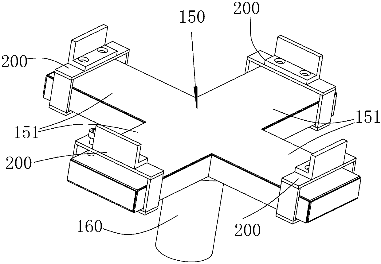
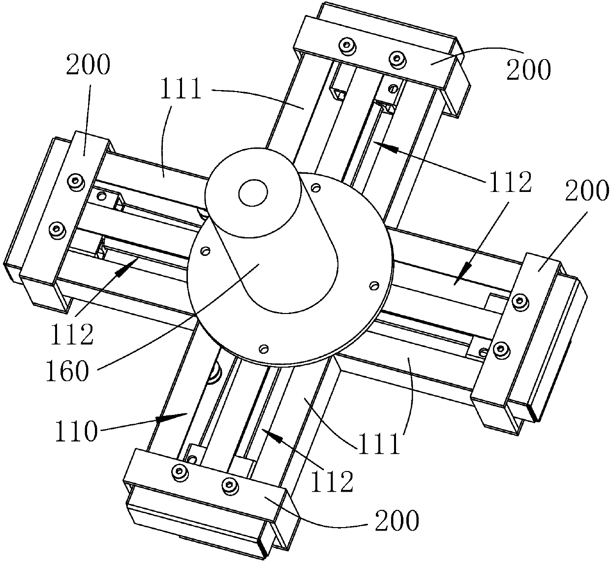
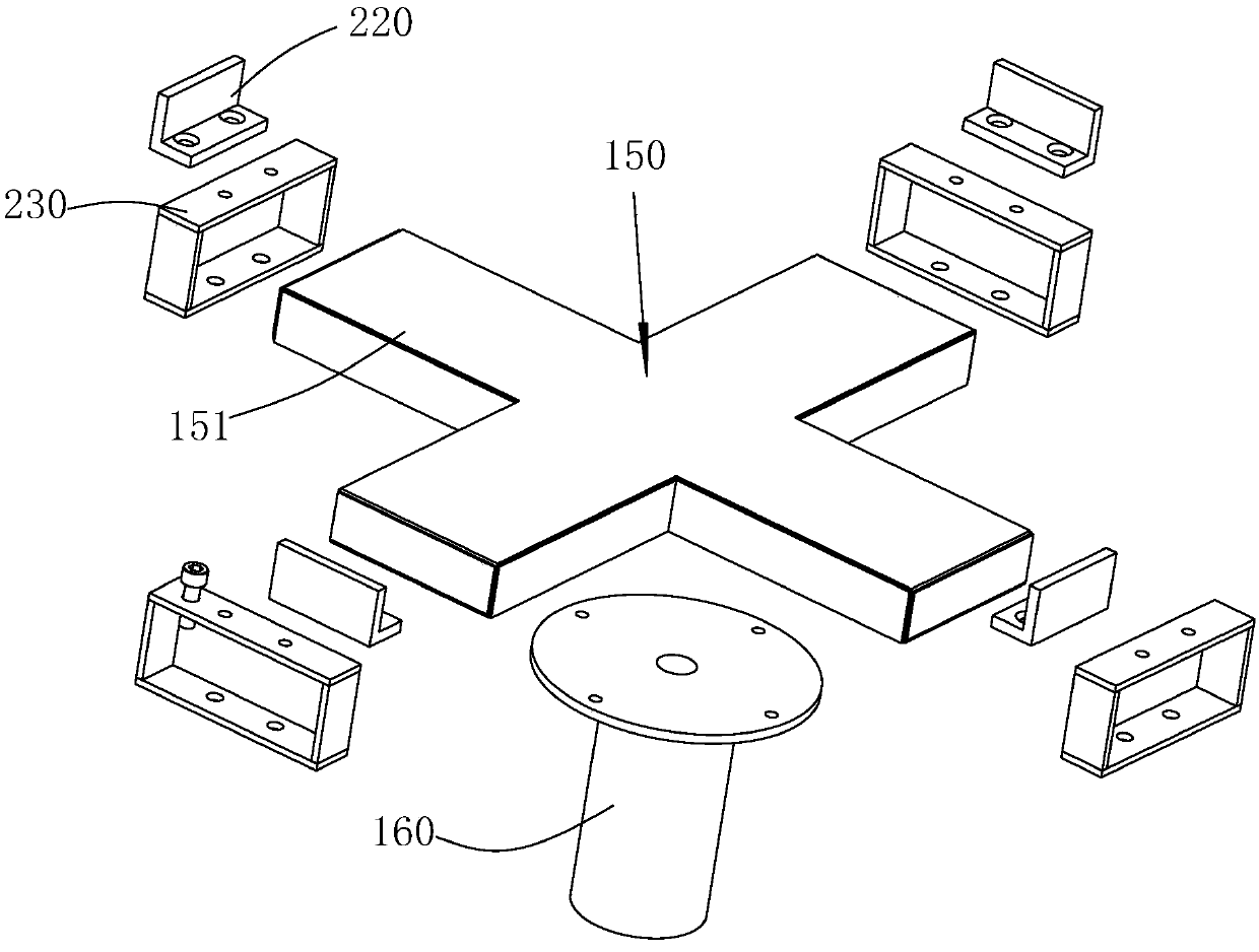
[0041] An embodiment of the present invention provides a clamping device, please refer to Figure 1-Figure 11 , the clamping device includes a mounting base, a plurality of sliding bodies 120 , a plurality of clamping pieces 200 and a linkage cable 130 .

[0042] In this embodiment, the mounting seat is the upper cover 150 of the clamping device, and the upper cover 150 is cross-shaped. Of course, in other embodiments of the present invention, the upper cover can also be square, Round and other shapes. In this embodiment, the upper cover 150 extends four upper arms 151 around, and the four upper arms 151 are evenly distributed within a range of 360°, and the angle between adjacent upper arms 151 is 90 degrees. In addition, in other embodiments of the present invention, the number of the upper support arms may also be other numbers, such as 2, 6, and so on. In addition, in other embodiments of the present invention, the mounting base may also be the bottom cover of the clamp...

no. 2 example

[0058] Figure 12 is a schematic diagram of the clamping device of the second embodiment of the present invention, Figure 12 The schematic diagram with figure 1 The schematic diagrams are similar, so the same component symbols represent the same components. The main difference between this embodiment and the first embodiment is the shape and structure of the clamping device.

[0059] See Figure 12-Figure 15 , in this embodiment, the overall shape of the clamping device is circular, specifically, the upper cover 350 and the bottom cover 310 are both circular. In this embodiment, the mounting seat is the bottom cover 310 of the clamping device, and four sliding bodies 320 are arranged above the bottom cover 310. Of course, in other embodiments of the present invention, the sliding The number of entities can also be other numbers, such as 2, 6, and so on. In this embodiment, the four sliding bodies 320 are T-shaped, and the four sliding bodies 320 are evenly distributed on...


PUM


Abstract

An embodiment of the invention discloses a clamping device. The clamping device comprises a mounting seat, multiple sliding bodies which are mounted on the mounting seat and extend in different directions, multiple clamping pieces which are assembled on the different sliding bodies separately, can slide on the sliding bodies and have the combined action to clamp a to-be-clamped piece, as well as linkage cables which are connected with the clamping pieces in a linked manner and drive the clamping pieces to slide on the respective sliding bodies. An embodiment of the invention further disclosesa clamping system. The clamping device and the clamping system have the advantages of capability of clamping to-be-clamped pieces in different sizes and relatively low cost.

Description

technical field [0001] The invention relates to a clamping device and a clamping system. Background technique [0002] In the current production, many processing techniques need to clamp and position the parts. At present, the clamping and positioning method of the parts is mainly to clamp the parts to be clamped by the clamping device to position them. However, the existing technology is generally Different sizes of parts to be clamped require different clamping devices. For example, different volumes of inner tanks require different clamping devices. For example, a 3L inner tank needs one type of clamping device to be clamped, and a 4L inner tank needs another clamping device. The clamping device of different specifications is clamped, and the 5L liner needs to be clamped by another clamping device of another specification. This leads to the need for too many clamping devices, leading to increased costs. Contents of the invention [0003] The technical problem to be so...

Claims


Application Information

Patent Timeline
IPC IPC(8): B25B11/00
CPCB25B11/00
Inventor 卫波荣刘传涛
Owner 杭州联堤智能科技有限公司
Learn More