
Improved air purification equipment

An air purification equipment and improved technology, applied in the field of air purification, can solve the problems of waste of power resources, poor plug stability, easy to generate arcs, etc., and achieve the effects of saving electricity, preventing electric shock accidents, and high safety.

Inactive Publication Date: 2018-04-10
深圳市汇呈实业有限公司
View PDF0 Cites 6 Cited by
  • Summary
  • Abstract
  • Description
  • Claims
  • Application Information

AI Technical Summary

Problems solved by technology

[0002] The fresh air fan is an effective air purification equipment that can circulate the indoor air. On the one hand, the indoor dirty air is discharged outside, and on the other hand, the fresh outdoor air is sterilized, disinfected, filtered and other measures, and then input into the room. , so that the room is full of fresh and clean air all the time. The fresh air fan uses the fresh air convection technology to achieve convection of the indoor air through independent air supply and induction, so as to maximize the indoor air replacement and ensure that it enters the room. The air is clean and healthy. However, due to the high voltage required in the working process of the fresh air blower, through the existing manual plugging power supply mode, the plugging stability is poor, and arcs are likely to be generated during the plugging process. The generation of arcs is likely to cause users Electric shock, which has certain potential dangers to users, will cause safety accidents and cause casualties. In addition, there are some fresh air fan equipment that can be automatically plugged in, but they need to be powered by the mains to control the propulsion when plugging in. The equipment is automatically plugged in and running, resulting in waste of power resources and large defects, which cannot meet the existing needs

Method used


Image

  • Improved air purification equipment
  • Improved air purification equipment
  • Improved air purification equipment

Examples


Embodiment Construction

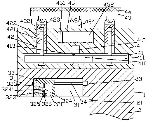
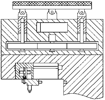
[0026] Such as Figure 1-Figure 9As shown, an improved air purification device of the present invention includes a body 1, a power storage part 4 and a plug 5 fixedly installed on the top end surface of the body 1, the body 1 is composed of a supporting part 2 and a pushing part 3, The bottom end surface of the pushing part 3 is provided with a pushing groove 31, and the first screw rod 34 extending left and right is arranged in the pushing groove 31, and the right end of the first screw rod 34 is connected with the first motor 33. , the said push groove 31 is provided with a push block 32 threadedly connected with said first screw rod 34, said push block 32 is provided with a first accommodating chamber 322, said first accommodating chamber 322 is right The push block 32 on the side is provided with a locking groove 321 whose bottom passes through the bottom end surface of the push block 32, and the right side end of the first accommodation chamber 322 is connected with the u...


PUM


Abstract

The invention discloses an improved air purification device, which comprises a machine body, a power storage part and a plug fixedly installed on the top end surface of the machine body, the machine body is composed of a supporting part and a pushing part, and a pushing groove is arranged in the bottom end surface of the pushing part. There is a first screw-shaped rod extended from left to right, the right end of the first screw-shaped rod is connected with the first motor, and a push block is arranged in the push groove to cooperate with the screw thread of the first screw-shaped rod. There is a first accommodation chamber, and a locking groove is provided in the push block on the right side of the first accommodation chamber, the bottom of which passes through the bottom end surface of the push block, and the right side end of the first accommodation chamber is connected with the upper left side of the locking groove. There are holes and grooves in the end surface of the bottom of the push block at the bottom of the accommodation chamber, and the first rotating pin shaft extended up and down is arranged in the first accommodation chamber; the invention has simple structure, convenient operation, automatic control of power supply plugging, and safe power supply plugging High safety, prevent electric shock accidents, supply power through solar power, energy saving and environmental protection, reduce use costs, and save electricity.

Description

technical field [0001] The invention relates to the technical field of air purification, in particular to an improved air purification device. Background technique [0002] The fresh air fan is an effective air purification equipment that can circulate the indoor air. On the one hand, the indoor dirty air is discharged outside, and on the other hand, the fresh outdoor air is sterilized, disinfected, filtered and other measures, and then input into the room. , so that the room is full of fresh and clean air all the time. The fresh air fan uses the fresh air convection technology to achieve convection of the indoor air through independent air supply and induction, so as to maximize the indoor air replacement and ensure that it enters the room. The air is clean and healthy. However, due to the high voltage required in the working process of the fresh air blower, through the existing manual plugging power supply mode, the plugging stability is poor, and arcs are likely to be gen...

Claims


Application Information

Patent Timeline
IPC IPC(8): F24F1/00F24F3/16F24F13/00H01R13/631H01R13/627
CPCF24F3/16F24F13/00H01R13/6278H01R13/631
Inventor 潘王琴
Owner 深圳市汇呈实业有限公司
Learn More