Fastening device

A technology of fastening device and fixing frame, which is applied to workpiece clamping devices, manufacturing tools, etc., can solve problems such as difficulty in positioning items on the chute, and achieve the effects of smooth horizontal movement, improved efficiency, and fast positioning speed.

Inactive Publication Date: 2018-04-06
HUDONG ZHONGHUA SHIPBUILDINGGROUP
View PDF7 Cites 2 Cited by
  • Summary
  • Abstract
  • Description
  • Claims
  • Application Information

AI Technical Summary

Problems solved by technology

[0003] In view of the deficiencies in the prior art, the purpose of the present invention is to provide a fastening device to solve the problem of difficult positioning of items on the existing chute

Method used


Image

  • Fastening device
  • Fastening device
  • Fastening device

Examples


Embodiment

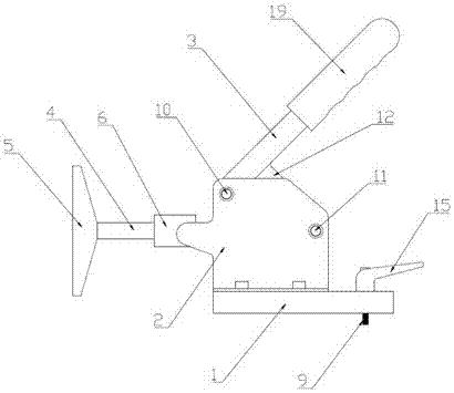
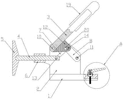
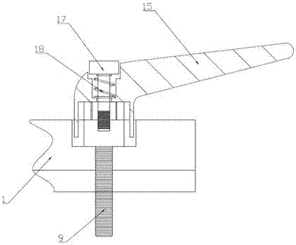
[0025] Example: such as Figure 1 to Figure 6 As shown, a fastening device includes a fixed seat 1, two fixed frames 2, a driving handle 3, a support rod 4, a support plate 5, a guide tube 6, a first driving piece 7, a second driving piece 8 and a locking Bolts 9, the two fixed frames 2 are vertically arranged on the upper surface of the fixed seat 1, the two fixed frames 2 are arranged oppositely, and the first fixed shaft 10 and the second fixed shaft 10 are arranged between the two fixed frames 2 Fixed shaft 11, the guide tube 6 is horizontally arranged on the left side of the two fixed frames 2, the right end of the support rod 4 passes through the guide tube 6 and stretches between the two fixed frames 2, the support rod 4 The left end is provided with a ball head, and the right side of the support plate 5 is provided with a ball bowl seat, and the ball head matches the ball bowl seat, and the ball head extends into the ball bowl seat. The lower end extends between the t...


PUM


Abstract

The invention discloses a fastening device, and belongs to the technical field of ship construction. The fastening device comprises a fixing seat, two fixing frames, a driving handle, a supporting rod, a supporting plate, a guiding tube, a first driving piece, a second driving piece and a locking bolt. The two fixing frames are vertically arranged on the upper surface of the fixing seat. The driving handle drives the supporting rod to move in the guiding tube horizontally through a first moving shaft and a second moving shaft so that the supporting plate is driven to move in the horizontal direction, and an object to be positioned is positioned conveniently and accordingly. The fixing seat is provided with a vertical bolt hole. The locking bolt is arranged in the vertical bolt hole in a penetrating mode. The lower end of the locking bolt extends to the lower portion of the fixing seat, the lower end of the locking bolt is connected with the bottom of a sliding groove so that the fastening device can be fixed to the sliding groove conveniently, and the fastening device can fix the positioned object firmly. The fastening device is simple in structure and convenient to use, can be repeatedly used, reduces the cost of ship construction and improves the efficiency of ship construction.

Description

technical field [0001] The invention belongs to the technical field of shipbuilding, in particular to a fastening device. Background technique [0002] During the construction of LNG ships, it is often necessary to place some workpieces on the chute for positioning. The existing method is to set a fixed bracket on the edge of the chute, set a screw and a handle on the bracket, and drive the screw on the chute through the handle. The workpiece is positioned. However, there are many shortcomings in the use of this method, and the working conditions are subject to many restrictions, which are specifically manifested in: (1) setting the screw and handle increases the size of the overall device, which cannot meet the requirements under the working conditions of movement or limited space; (2) This positioning method manually drives the handle, which has low efficiency and poor positioning effect. (3) Too long screw rod length can easily lead to deformation and other conditions, r...

Claims


Application Information

Patent Timeline
Patent Type & Authority Applications(China)
IPC IPC(8): B25B11/00
CPCB25B11/00
Inventor 徐军邬昌平谢妤孙明
Owner HUDONG ZHONGHUA SHIPBUILDINGGROUP
Why Eureka
Try Eureka