
Laser marking machine

A laser marking machine and laser technology are applied in the field of laser marking machines to achieve the effects of being beneficial to structure, simplification and distance control

Inactive Publication Date: 2018-04-06
苏州威百斯特智能科技有限公司
View PDF4 Cites 2 Cited by
  • Summary
  • Abstract
  • Description
  • Claims
  • Application Information

AI Technical Summary

Problems solved by technology

[0002] The transportation track in the prior art mainly includes two support plates and a conveyor belt installed on the inside of the support plates, wherein the positions of the two support plates are relatively fixed, so that the transport track in the prior art can only transport two pieces with a width equal to The product of the distance between the support plates
In actual production, the sizes of various products may be different. Therefore, the transportation track with the relatively fixed positions of the two support plates cannot transport products of different sizes.

Method used


Image

  • Laser marking machine
  • Laser marking machine
  • Laser marking machine

Examples


Embodiment Construction

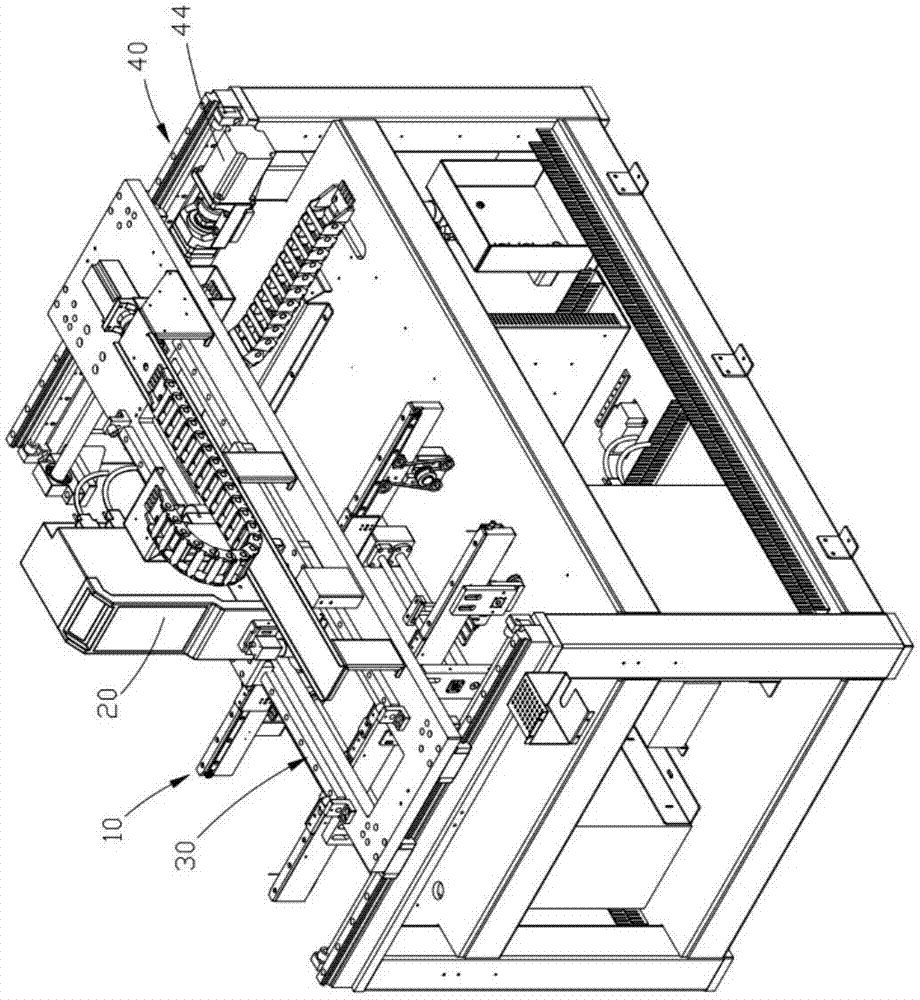
[0046] The following content reference Figure 1 to Figure 13 .

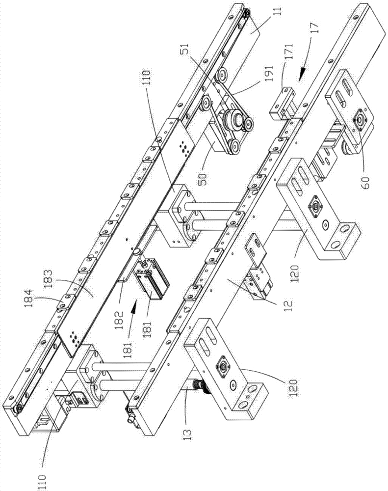
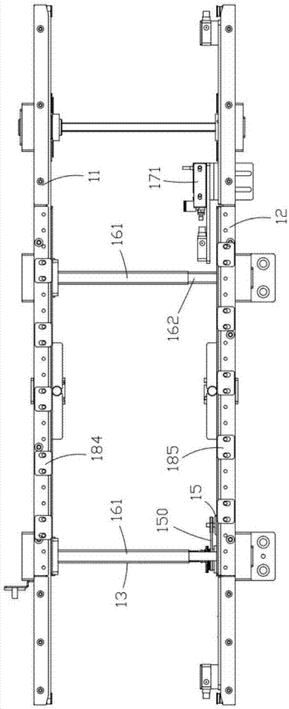
[0047] A laser marking machine, comprising a product transport track 10 and a laser 20 positioned above the product transport track, the product transport track includes a pair of support plates arranged side by side, a conveyor belt arranged inside the pair of support plates, a pair of support plates The second support plate 12 in the plate is fixedly arranged, and the first support plate 11 in a pair of support plates is installed on the transverse movement block 110, and the transverse movement block is provided with threaded sleeve 13, and threaded sleeve cooperates with screw rod 14, and screw rod It is connected with the transmission device a, and a guide assembly is arranged on the lateral moving block.

[0048] The second support plate 12 is installed on the support plate support 120, and the transmission device a is installed on the support plate support; the guide assembly includes a common sleeve 161...


PUM


Abstract

A laser marking machine comprises a product conveying track and a laser device located above the product conveying track; the laser device is mounted on a longitudinal driving device; the longitudinaldriving device is mounted on a transverse driving device; the moving direction of the longitudinal driving device driven by the transverse driving device is identical with that of products conveyed by the product conveying track; and the product conveying track has the adjustable width. During operation, the product conveying track is adjusted to the proper size to adapt to the size of products,and the products are blocked by a lifting type blocking device and positioned by a positioning device when advancing to the predetermined position along the product conveying track; longitudinal and transverse positions of the laser device are adjusted under driving of the transverse driving device and the longitudinal driving device, the laser device is aligned to the products vertically under assistance of an industrial camera, and laser marking is performed on the products by the laser device.

Description

technical field [0001] The invention relates to the technical field of precision machinery, in particular to a laser marking machine. Background technique [0002] The transportation track in the prior art mainly includes two support plates and a conveyor belt installed on the inside of the support plates, wherein the positions of the two support plates are relatively fixed, so that the transport track in the prior art can only transport two pieces with a width equal to The product of the distance between the supports. However, in actual production, the sizes of various products may be different. Therefore, the transportation track with the relatively fixed positions of the two support plates cannot transport products of different sizes. Contents of the invention [0003] The technical problem solved by the invention is how to adjust the width of the transport track of the laser marking machine to adapt to products of different sizes. [0004] In order to solve the above...

Claims


Application Information

Patent Timeline
Patent Type & Authority Applications(China)
IPC IPC(8): B23K26/362B23K26/70
CPCB23K26/361B23K26/702
Inventor 郭飞
Owner 苏州威百斯特智能科技有限公司
Learn More