
Flexible substrate, state detecting method thereof and display device

A flexible substrate and state detection technology, applied in identification devices, static indicators, instruments, etc., can solve the problems of pin cutting, large tearing, cutting flexible substrates in the binding area, etc., to improve cutting accuracy, avoid The effect of cutting damage and avoiding material waste

Active Publication Date: 2018-03-30
WUHAN TIANMA MICRO ELECTRONICS CO LTD
View PDF6 Cites 2 Cited by
  • Summary
  • Abstract
  • Description
  • Claims
  • Application Information

AI Technical Summary

Problems solved by technology

[0004] When the edge of the flexible substrate is slightly torn, after it is bound to the display panel, the tearing degree of the edge will become larger and larger, which will affect the installation stability of the flexible substrate, and then affect the normal display of the display panel
When the edge of the flexible substrate is cut off, it will cause the pins in the binding area to be cut, and after it is bound to the display panel, it will also affect the normal display of the display panel
Moreover, when the edge of the flexible substrate is abnormal due to the cutting process, if it is not detected in time, it will lead to subsequent cutting of many problematic flexible substrates, resulting in waste of materials

Method used


Image

  • Flexible substrate, state detecting method thereof and display device
  • Flexible substrate, state detecting method thereof and display device
  • Flexible substrate, state detecting method thereof and display device

Examples


Embodiment Construction

[0029] In order to better understand the technical solutions of the present invention, the embodiments of the present invention will be described in detail below in conjunction with the accompanying drawings.

[0030] It should be clear that the described embodiments are only some of the embodiments of the present invention, not all of them. Based on the embodiments of the present invention, all other embodiments obtained by persons of ordinary skill in the art without creative efforts fall within the protection scope of the present invention.

[0031] Terms used in the embodiments of the present invention are only for the purpose of describing specific embodiments, and are not intended to limit the present invention. As used in the embodiments of the present invention and the appended claims, the singular forms "a", "said" and "the" are also intended to include the plural forms unless the context clearly indicates otherwise.

[0032] It should be understood that the term "an...


PUM


Abstract

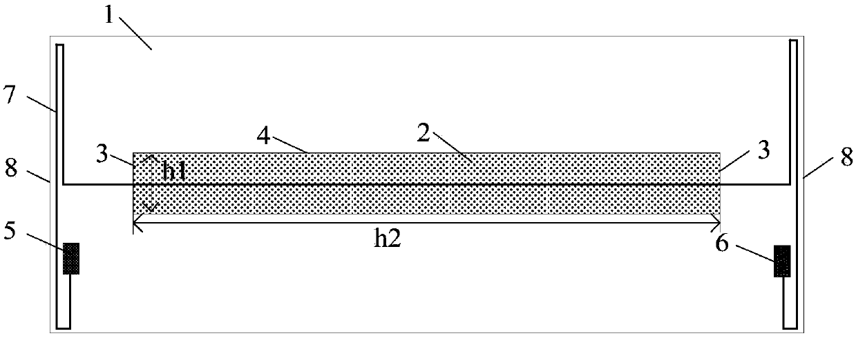
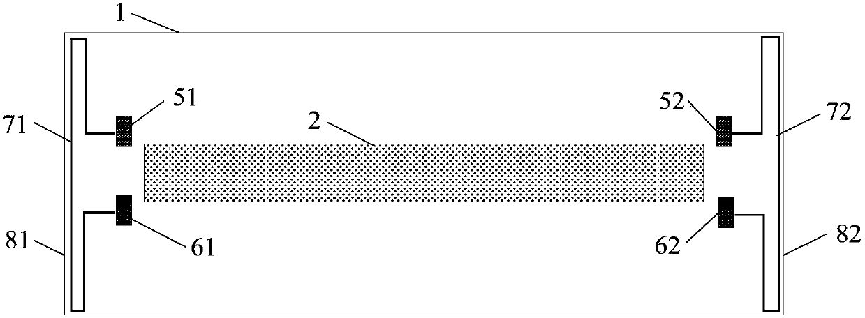
The embodiment of the invention provides a flexible substrate, a state detecting method thereof and a display device and relates to the field of display technology. The state detecting method of the flexible substrate can timely and effectively detect the state of the flexible substrate. The flexible substrate comprises a base substrate, a driving chip arranged on the base substrate, at least onedetecting terminal group arranged on the base substrate, and metal wires connecting the target signal receiving ends and the detecting signal output ends of the detecting terminal groups, wherein theedge of the driving chip is composed of first edges and second edges which are perpendicular to each other, and the length of the first edges is smaller than that of the second edges; every detectingterminal group is composed of one target signal receiving end and one detecting signal output end; the metal wires in partial areas extend along the third edges of the base substrate within a preset distance range, and the third edges are adjacent to one of the first edges, and in the extending direction of the second edges, one of the third edges, one of the first edge, the other first edge and the other third edge are sequentially arranged.

Description

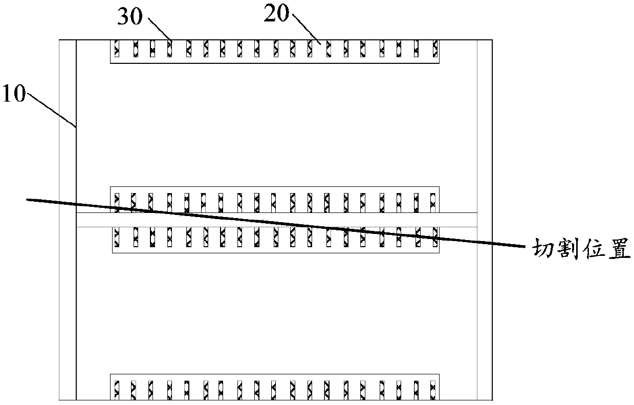
【Technical field】 [0001] The invention relates to the field of display technology, in particular to a flexible substrate, a state detection method thereof, and a display device. 【Background technique】 [0002] In order to reduce the frame width of the display panel, the driver chip on the display panel is usually arranged on a flexible substrate, and then the flexible substrate provided with the driver chip is bound to the display panel and bent towards the back side of the display panel to The narrow frame design of the display device is realized. [0003] In the production process of flexible substrates, such as figure 1 As shown, the flexible substrate 10 is shipped in the form of a coil, which is cut into individual flexible substrates through a cutting process, and then bound into the display panel. However, during the cutting process, the edge of the flexible substrate may be slightly torn, or the edge may be cut off due to low cutting precision. For example, when c...

Claims


Application Information

Patent Timeline
Patent Type & Authority Applications(China)
IPC IPC(8): G09G3/00G09F9/30
CPCG09F9/301G09G3/006
Inventor 杨毅志纪文套
Owner WUHAN TIANMA MICRO ELECTRONICS CO LTD
Learn More