
Comprehensive tire abrasion testing machine

A comprehensive test and tire technology, applied in the direction of testing wear resistance, measuring devices, instruments, etc., can solve problems such as the inability to adapt to high-speed tire testing, the failure of flat belt testing machines to be widely used, and the easy fatigue damage of steel belts.

Active Publication Date: 2018-03-30
HARBIN INST OF TECH AT WEIHAI
View PDF6 Cites 13 Cited by
  • Summary
  • Abstract
  • Description
  • Claims
  • Application Information

AI Technical Summary

Problems solved by technology

(1) Flat tire testing machine: It is suitable for the study of the mechanical properties of tires at low speeds; it can only perform tests at relatively small speeds, resulting in the flat tire testing machine being basically unable to adapt to high-speed tire testing, and few people use it as a tire wear test
(2) Flat-belt tire testing machine: It overcomes the shortcomings of the flat-plate type, and can carry out mechanical research at high speeds. It also has a certain application range; but its cost is very high, and it is mostly used by large tire suppliers. The steel belt is easy to use. Fatigue damage, so the application of the flat belt testing machine has not been widely used
(3) Traditional drum tire testing machine: suitable for the study of steady and unsteady mechanical properties of tires at high and low speeds; the surface of the drum has curvature, which is different from the real road surface, and can only be tested when the diameter of the drum is large enough. Neglecting the influence of the curvature of the drum surface, the equipment is bulky

Method used


Image

  • Comprehensive tire abrasion testing machine
  • Comprehensive tire abrasion testing machine
  • Comprehensive tire abrasion testing machine

Examples


Embodiment Construction

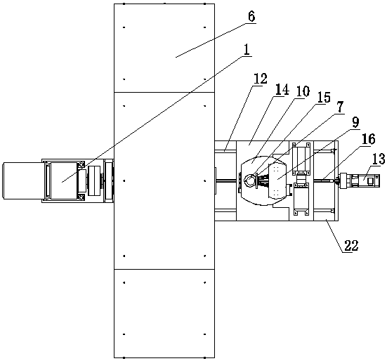
[0017] Such as Figure 1-4 The tire wear comprehensive testing machine shown is provided with a frame 6, on which a rotating shaft 2 is installed via a bearing, and a power source 1 is provided on the frame behind the rotating shaft 2, and the power source 1 is connected to the rotating shaft 2 through a transmission device ,From figure 1 It can be seen from the figure that the power source 1 is a servo motor, the output shaft of the servo motor is provided with a driving pulley, the rotating shaft 2 at the rear side of the frame is provided with a driven pulley, and there is a drive pulley between the driving pulley and the driven pulley Drive belt; the rotating shaft on the front side of the frame 6 is fixedly connected with a turntable 4, and the turntable 4 is fixed with a drum 5, and the front side of the drum 5 is provided with a circular test groove 3 coaxial with the rotating shaft 2; The frame on the side is provided with a side deflection table, and the side deflect...


PUM


Abstract

The invention provides a comprehensive tire abrasion testing machine and relates to the technical field of tire abrasion testing machines. The comprehensive tire abrasion testing machine comprises a frame, wherein a rotation shaft is mounted on the frame; a power source is arranged and is connected with the rotation shaft through a transmission device; a rotation drum is arranged on the rotation shaft on the front side of the frame; a circular testing groove coaxial with the rotation shaft is formed in the rotation drum; a lateral deflection table is arranged on the front side of the rotationdrum and is connected with a rotation table driving device used for driving the lateral deflection table to rotate; a tire loading frame is arranged on the lateral deflection table; a guide rail is arranged on the tire loading frame; a sliding seat is arranged on the guide rail; a sliding seat driving device is arranged and is connected with the sliding seat; a tire shaft is arranged on the sliding seat; a wheel hub mounting disc is arranged at the end of the tire shaft; a force measuring sensor is arranged between the sliding seat driving device and the sliding seat. The comprehensive tire abrasion testing machine has the advantages that the tire is internally tangent to the road surface, the volume is small, the production cost and the usage cost are low, and the testing results are accurate.

Description

technical field [0001] The invention relates to the technical field of tire wear testing machines, in detail, it is a comprehensive tire wear testing machine which is inscribed with the road surface, the road surface can be replaced, is easy to use, can accurately measure the tire wear performance, and has great reference value for the use of tires. Background technique [0002] We know that the wear resistance of tires is the most important factor in determining the durability of tires. More than 98% of today's car tires are replaced or scrapped because of polishing. Therefore, wear has become the most concerned topic in tire design and production technology. The wear phenomenon of the tire is not only determined by the wear resistance of the tread rubber, but also greatly affected by the tire structure and pattern. Especially in the use of tires, the most common phenomenon of eccentric wear mostly begins to appear after the tire has been rotated for millions of times. T...

Claims


Application Information

Patent Timeline
Patent Type & Authority Applications(China)
IPC IPC(8): G01N3/56G01N3/02
CPCG01N3/02G01N3/56
Inventor 吴健粟本龙王友善陈龙崔志博
Owner HARBIN INST OF TECH AT WEIHAI
Learn More