Metallic magnesium smelting reduction furnace charging equipment

A reduction furnace and metal magnesium technology, which is applied in the field of magnesium smelting reduction furnace charging equipment, can solve the problems of severe vibration between the reel and the engine, unfavorable loading car, wear at the bottom of the machine, etc., to protect the machine base and reduce Risk of tipping over, friction reduction effect

Pending Publication Date: 2018-03-30
蓝婷
View PDF4 Cites 0 Cited by
  • Summary
  • Abstract
  • Description
  • Claims
  • Application Information

AI Technical Summary

Problems solved by technology

[0002] The purpose of the blast furnace feeding equipment is to transport the proportioned and weighed furnace charge to the top of the blast furnace according to the production process requirements. The blast furnace feeding equipment is mainly the blast furnace feeding machine. There are two kinds of feeder loading machine and belt feeding machine; the existing charging equipment for metal magnesium smelting reduction furnace has certain disadvantages in use. First, the steel rope becomes extremely difficult to pull due to long-term friction, and The shortening of the service life has a certain adverse effect. Secondly, raw materials may be spilled from the loading truck during the transportation and fall on the rails, which is not conducive to the forward movement of the loading truck and may easily cause the risk of overturning. In addition, When the winch is working, it will bring about severe vibration of the reel and the engine, which will cause wear to the bottom of the machine and have a certain impact on people's use. Therefore, we propose a furnace charging equipment for metal magnesium smelting reduction furnace

Method used


Image

  • Metallic magnesium smelting reduction furnace charging equipment
  • Metallic magnesium smelting reduction furnace charging equipment
  • Metallic magnesium smelting reduction furnace charging equipment

Examples


Embodiment Construction

[0028] In order to make the technical means, creative features, objectives and effects of the present invention easy to understand, the present invention will be further explained below in conjunction with specific embodiments.

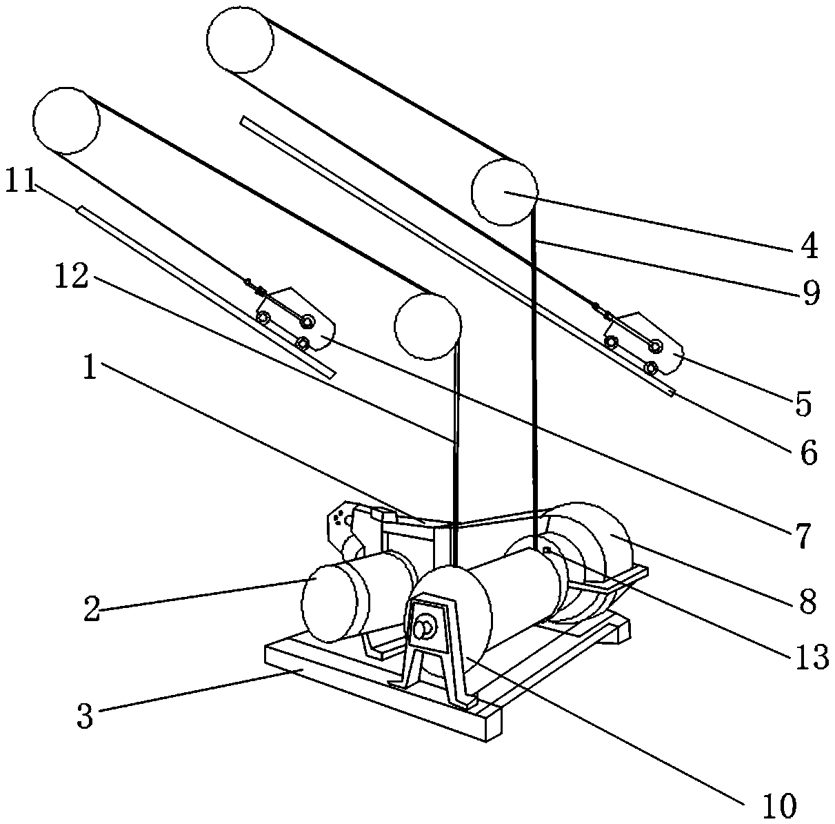
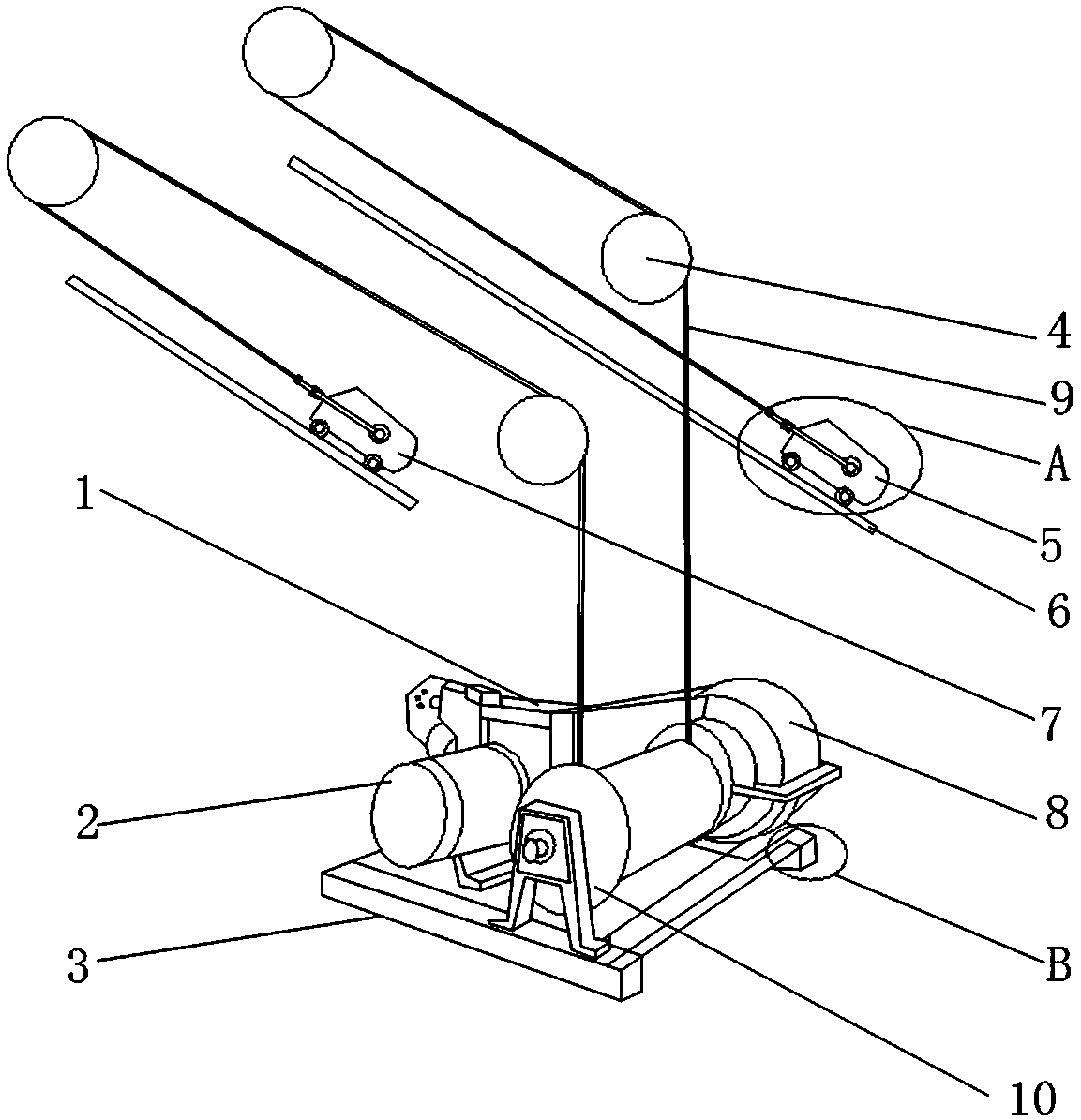
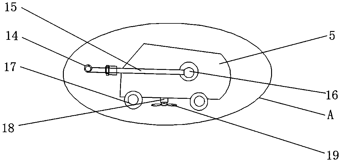
[0029] Such as Figure 1-4 As shown, a metal magnesium smelting reduction furnace charge charging equipment includes a rope wheel 4 and a No. 1 loading car body 5. The outer surface of the upper end of the drum 10 is movably connected with a No. 1 steel rope 9 and a No. 2 steel rope 12. And the No. 1 steel rope 9 and the No. 2 steel rope 12 are fixedly connected, a lubricating oil port 13 is fixedly installed on the outer surface of one end of the reel 10, the engine 2 is fixedly installed on the outer surface of the rear end of the reel 10, and the upper end of the engine 2 A brake 1 is fixedly connected to the surface, a reducer 8 is fixedly connected to the outer surface of one end of the brake 1, a hoist frame 3 is fixedly installed on the outer surf...


PUM


Abstract

The invention discloses metallic magnesium smelting reduction furnace charging equipment which comprises rope sheaves and a No.1 loading vehicle body, wherein a No.1 steel rope and a No.2 steel rope are movably connected with the outer surface of the upper end of a roller; a lubricating oil port is fixedly mounted on the outer surface of one end of the roller; an engine is fixedly mounted on the outer surface of the rear end of the roller; a brake is fixedly connected with the outer surface of the upper end of the engine; a speed reducer is fixedly connected with the outer surface of one end of the brake; a winch rack is fixedly mounted on the outer surface of the lower end of the engine; and the corresponding rope sheaves are movably connected with the outer surface of one side of the No.1 steel rope. The metallic magnesium smelting reduction furnace charging equipment disclosed by the invention is equipped with the lubricating oil port, fans and a buffer spring, so that the normal operation of the steel ropes can be guaranteed during the furnace charging process; meanwhile, a raw material left on steel rails can be effectively removed; and furthermore, the vibration generation during the operation of a winch can be reduced and a better use prospect can be brought.

Description

Technical field [0001] The invention relates to the field of furnace charging equipment for a magnesium smelting reduction furnace, in particular to a furnace charging equipment for a magnesium smelting reduction furnace. Background technique [0002] The purpose of the blast furnace charging equipment is to transport the proportioned and weighed charge to the top of the blast furnace according to the production process requirements. The blast furnace charging equipment is mainly a blast furnace charging machine. At present, the blast furnace charging machine used at home and abroad mainly has a rail type There are two kinds of feeder feeder and belt feeder; the existing charging equipment for magnesium smelting reduction furnace has certain disadvantages when used. First, the steel rope becomes extremely difficult to pull due to long-term friction, and The shortening of the service cycle has certain adverse effects. Secondly, raw materials may be spilled from the loading car dur...

Claims


Application Information

Patent Timeline
IPC IPC(8): F27D3/00C22B26/22C10M169/04C10N30/06C10N30/04
CPCF27D3/0084C10M169/048C22B26/22F27D2003/0065C10M2223/06C10M2215/06C10M2215/224C10M2215/04C10M2219/024C10M2217/044C10M2219/042C10M2207/144C10M2209/102C10M2203/1006C10M2201/05C10N2030/04C10N2030/06C10N2020/02C10N2010/02C10N2010/04
Inventor 蓝婷
Owner 蓝婷
Why Eureka
Try Eureka