Humidistat machine

A technology of constant humidity machine and body, which is applied in the field of constant humidity machine and can solve the problems that the air humidification effect cannot be realized at the same time

Inactive Publication Date: 2018-03-30
SHANGHAI NICHOLS ELECTRONICS TECH INC
View PDF0 Cites 8 Cited by
  • Summary
  • Abstract
  • Description
  • Claims
  • Application Information

AI Technical Summary

Problems solved by technology

[0004] However, the existing dehumidifiers can only dehumidify the air, but cannot simultaneously humidify the air.

Method used


Image

  • Humidistat machine

Examples


Embodiment Construction

[0019] In order to make the technical means, technical features, invention objectives and technical effects realized by the present invention easy to understand, the present invention will be further described below in conjunction with specific illustrations.

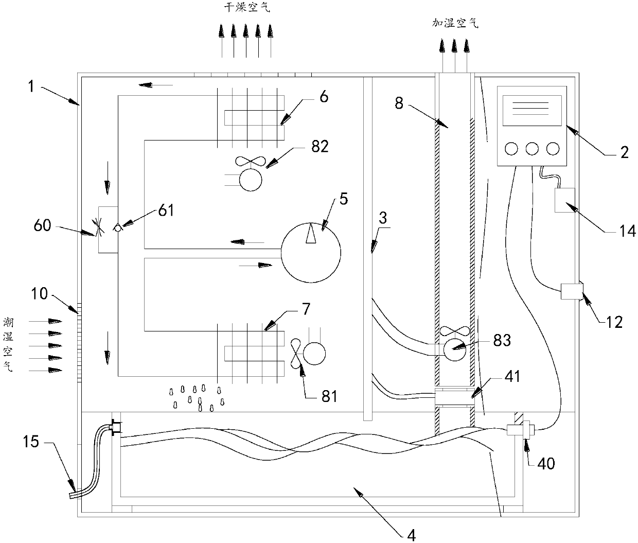
[0020] Such as figure 1 Shown is a constant humidity machine of the present invention, including a body 1 , a control system 2 , a partition 3 , a water storage tank 4 , a compressor 5 , an evaporator 6 and a condenser 7 .

[0021] In the present invention, an air inlet 10 is arranged on the left side of the body 1 through which humid air can enter; an air outlet 11 is arranged on the top of the body 1 through which dry air can be sent out.

[0022] In order to realize the indoor humidification effect, a temperature and humidity detection probe 12 is also provided on the right side of the body 1. According to the signal detected by the temperature and humidity detection probe 12, it is sent to the control system to auto...


PUM


Abstract

The invention discloses a constant humidity machine, which comprises a machine body, and also includes a control system, a partition, a water storage tank, a compressor, an evaporator and a condenser; The body chamber is divided into a left chamber and a right chamber; the water storage tank is located at the bottom of the body chamber; the compressor, evaporator, and condenser are located in the left chamber and are connected to the control system connected; the evaporator and condenser are connected to the compressor pipeline; an air inlet is provided on the left side of the body, and an air outlet is provided on the top of the body. The present invention can realize the effect of dehumidification or humidification through the temperature and humidity detection probe. The air humidification of the present invention is to atomize the water through the vibration of the atomizer sheet, and the humidification pipe is blown out by the third fan, thereby realizing indoor humidification. And the control system detects the temperature and humidity in the room according to the temperature and humidity detection probe, so as to automatically realize humidification or dehumidification.

Description

technical field [0001] The invention relates to a dehumidification and humidification system, in particular to a constant humidity machine. Background technique [0002] Dehumidifiers are also known as dehumidifiers, dryers, and dehumidifiers. They can generally be divided into two categories: civil dehumidifiers and industrial dehumidifiers, and belong to a part of the air-conditioning family. [0003] Its working principle is: the humid air is drawn into the machine by the fan, and passes through the heat exchanger. At this time, the water molecules in the air condense into water droplets, and the dried air after treatment is discharged outside the machine. This cycle keeps the indoor humidity at a suitable level. Relative humidity. [0004] However, the existing dehumidifiers can only dehumidify the air, but cannot simultaneously achieve the effect of humidifying the air. Contents of the invention [0005] The purpose of the present invention is to solve the problems ...

Claims


Application Information

Patent Timeline
Patent Type & Authority Applications(China)
IPC IPC(8): F24F3/14F24F11/89
CPCF24F3/14
Inventor 陈金恩李文先陈庆云
Owner SHANGHAI NICHOLS ELECTRONICS TECH INC
Why Eureka
Try Eureka