
Mixer increasing conglomeration rate

A technology of mixer and ball forming rate, which is applied in the field of improving the ball forming rate, can solve the problems of unreasonable water adding position, small balls cannot roll and grow, and non-compliance, etc., to achieve homogeneous production, uniform and stable water, The effect of increasing the thickness of the material layer

Pending Publication Date: 2018-03-30
WUHU XINXING DUCTILE IRON PIPES
View PDF7 Cites 2 Cited by
  • Summary
  • Abstract
  • Description
  • Claims
  • Application Information

AI Technical Summary

Problems solved by technology

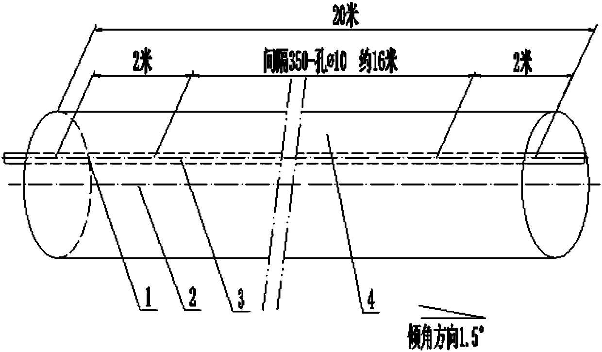
[0004] 1. Use the steel wire rope 4 to hang the water supply pipe 1. Since waste water and steam are added to the cylinder body 2, the accumulated material in the cylinder body 2 will cause the steel wire rope 4 to move back and forth, and the steel wire rope 4 is easy to break, causing the mixer to stop;
[0005] 2. The position of adding water is unreasonable, the effect of mixing and forming balls is poor, some mineral powders are only surface water, and some mineral powders are in the shape of muddy lumps;
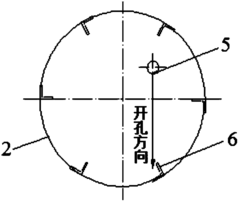
[0006] 3. The water filling hole in the opening area 3, that is, the layout of the Φ10 opening 5 is unreasonable, and water cannot be added according to the principle of the movement track of the mineral powder;
[0007] 4. The spray water in the water injection hole is columnar, which does not meet the requirements of the process of "dropping water into balls and atomizing to grow up";
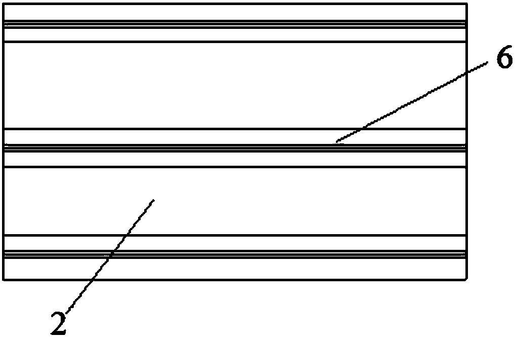
[0008] 5. The mineral powder advances in a spiral manner according to the process requirements. In the existing method, the cylinder is directly connected to the angle steel 6 as a lifting plate. The mineral powder cannot advance in a spiral manner, and the small balls cannot achieve the effect of rolling and growing.

Method used


Image

  • Mixer increasing conglomeration rate
  • Mixer increasing conglomeration rate
  • Mixer increasing conglomeration rate

Examples


Embodiment Construction

[0033] The specific implementation of the present invention will be described in further detail below by describing the embodiments with reference to the accompanying drawings, so as to help those skilled in the art have a more complete, accurate and in-depth understanding of the inventive concepts and technical solutions of the present invention.

[0034] Such as Figure 4 , Figure 5 with Image 6 The structure of the present invention shown is a mixer that improves the ball forming rate, and is an improved solution for improving the ball forming rate of the mixer. This mixing machine comprises the spray pipe 1 in cylinder body 2 and cylinder body 2 that is close to horizontal arrangement; On described cylinder body 2 inner wall, be provided with angle steel 6, described angle steel 6 is parallel to the axis of cylinder body 2, and Evenly distributed in the circumferential direction of the cylinder 2. The total length of the cylinder 2 is 20 m.

[0035] In order to overc...


PUM

PropertyMeasurementUnit
pore sizeaaaaaaaaaa

Abstract

The invention discloses a mixer increasing conglomeration rate. The mixer increasing conglomeration rate comprises a barrel body (2) arranged in a nearly-horizontal manner and a spraying pipe (1) in the barrel body (2); the inner wall of the barrel body (2) is provided with angle steel (6) which is parallel with the axis of the barrel body (2), and is distributed uniformly in the circumferential direction of the barrel body (2); a large beam (4) is arranged in the barrel body (2); and the spraying pipe (1) is fixed to the large beam (4). The technical scheme is adopted, the conglomeration rateof ore powder is increased, the gas permeability of ore powder of the same kind is greatly improved under the same work condition, and it is very favorable for increasing the material layer thickness; the water of a mixed material of an outlet of the barrel body is uniform and stable, the local material drying and local mud pie phenomenon is eliminated, and a sintering machine can achieve homogeneous production easily; and after a large beam structure replaces a steel wire rope device, accidents caused by breakage of a steel wire rope are eliminated.

Description

technical field [0001] The invention belongs to the technical field of ironmaking production equipment. More specifically, the present invention relates to a mixer with improved pelleting rate. Background technique [0002] The main function of the mixer is to mix and form balls. Adding water to the mixer plays an extremely important role in sintering production. On the one hand, it is required to add water uniformly and stably, and the equipment is reliable in operation without affecting the operating rate of the mixer itself; Sinter layer thickness. [0003] Such as figure 1 , figure 2 with image 3 Shown, in prior art, the shortcoming of mixing machine water adding device is: [0004] 1. Use the steel wire rope 4 to hang the water supply pipe 1. Since waste water and steam are added to the cylinder body 2, the accumulated material in the cylinder body 2 will cause the steel wire rope 4 to move back and forth, and the steel wire rope 4 is easy to break, causing the ...

Claims


Application Information

Patent Timeline
Patent Type & Authority Applications(China)
IPC IPC(8): C22B1/24
CPCC22B1/2406
Inventor 顾凤年
Owner WUHU XINXING DUCTILE IRON PIPES
Learn More