
Analog beamforming devices

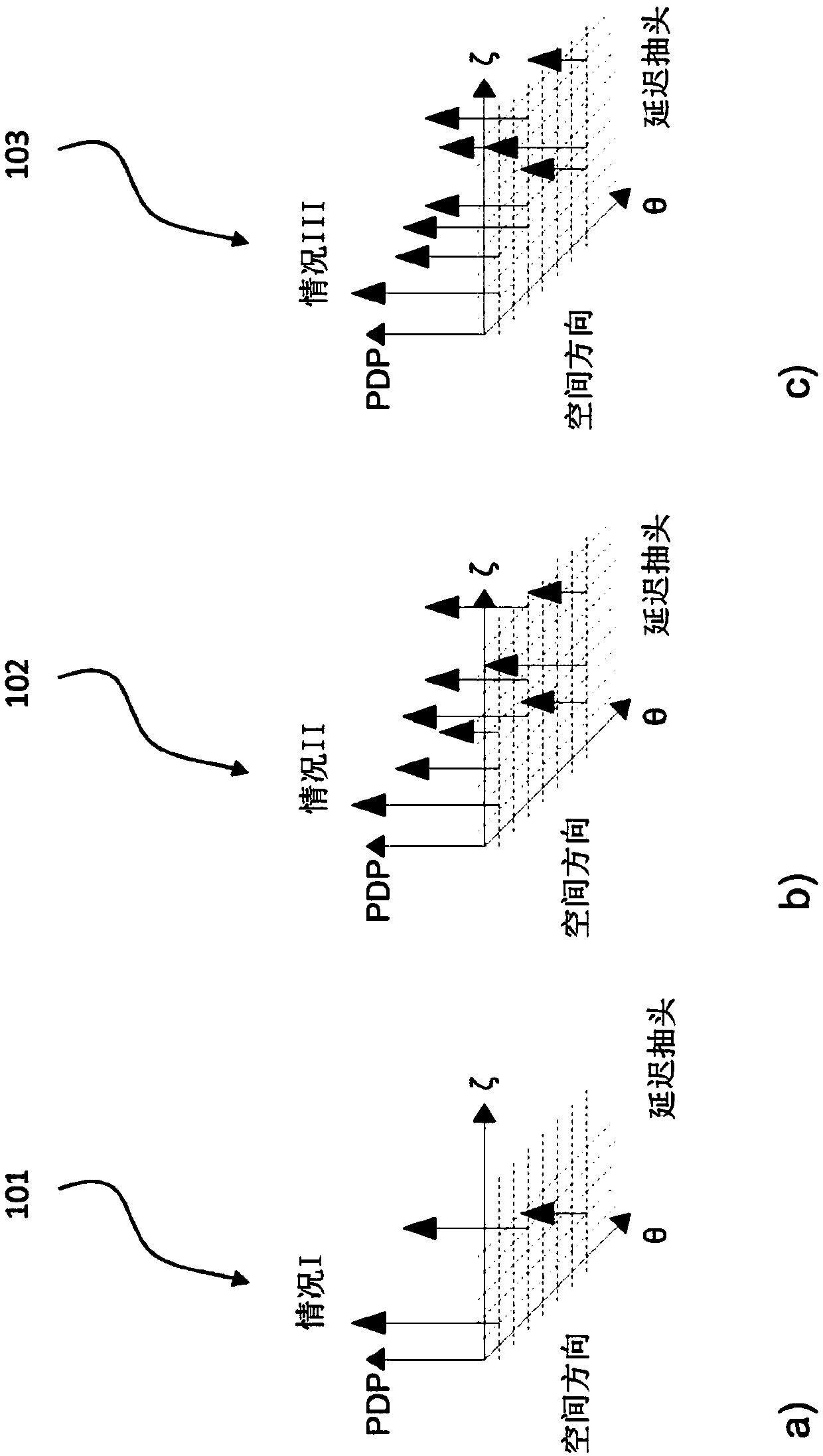
A beamforming and analog beam technology, applied in the field of analog beamforming transmitters and analog beamforming receivers, can solve the problems of small diffraction effect, enhancement, and reduction of fading effect.

Inactive Publication Date: 2018-03-27
HUAWEI TECH CO LTD
View PDF16 Cites 6 Cited by
  • Summary
  • Abstract
  • Description
  • Claims
  • Application Information

AI Technical Summary

Problems solved by technology

As a result, rough surface scattering effects are enhanced, reflections become more specular, and diffraction effects are very small
Additionally, path loss increases due to high free space attenuation
Penetration losses through building materials are significantly higher than in lower frequency bands, limiting indoor communication range mostly to indoor applications
Due to this loss of penetration, non-line-of-sight (NLOS) transmission becomes more challenging than in lower frequency bands
[0003] mmWave channels are often considered "deterministic" because the fading effects introduced by the superposition of different paths are greatly reduced compared to lower frequency bands

Method used


Image

  • Analog beamforming devices
  • Analog beamforming devices
  • Analog beamforming devices

Examples


Embodiment Construction

[0178] In the following detailed description, reference is made to the accompanying drawings, which form a part hereof, and show by way of illustration specific aspects in which the disclosure may be practiced. It is to be understood that other aspects may be utilized and structural or logical changes may be made without departing from the scope of the present disclosure. Accordingly, the following detailed description is not to be considered limiting, and the scope of the present disclosure is defined by the appended claims.

[0179] It should be understood that statements made in connection with a described method are also true with respect to a corresponding device or system configured to perform the method, and vice versa. For example, if specific method steps are described, a corresponding device may include units for performing the described method steps even if such units are not explicitly described or shown in the figures. Furthermore, it should be understood that th...


PUM


Abstract

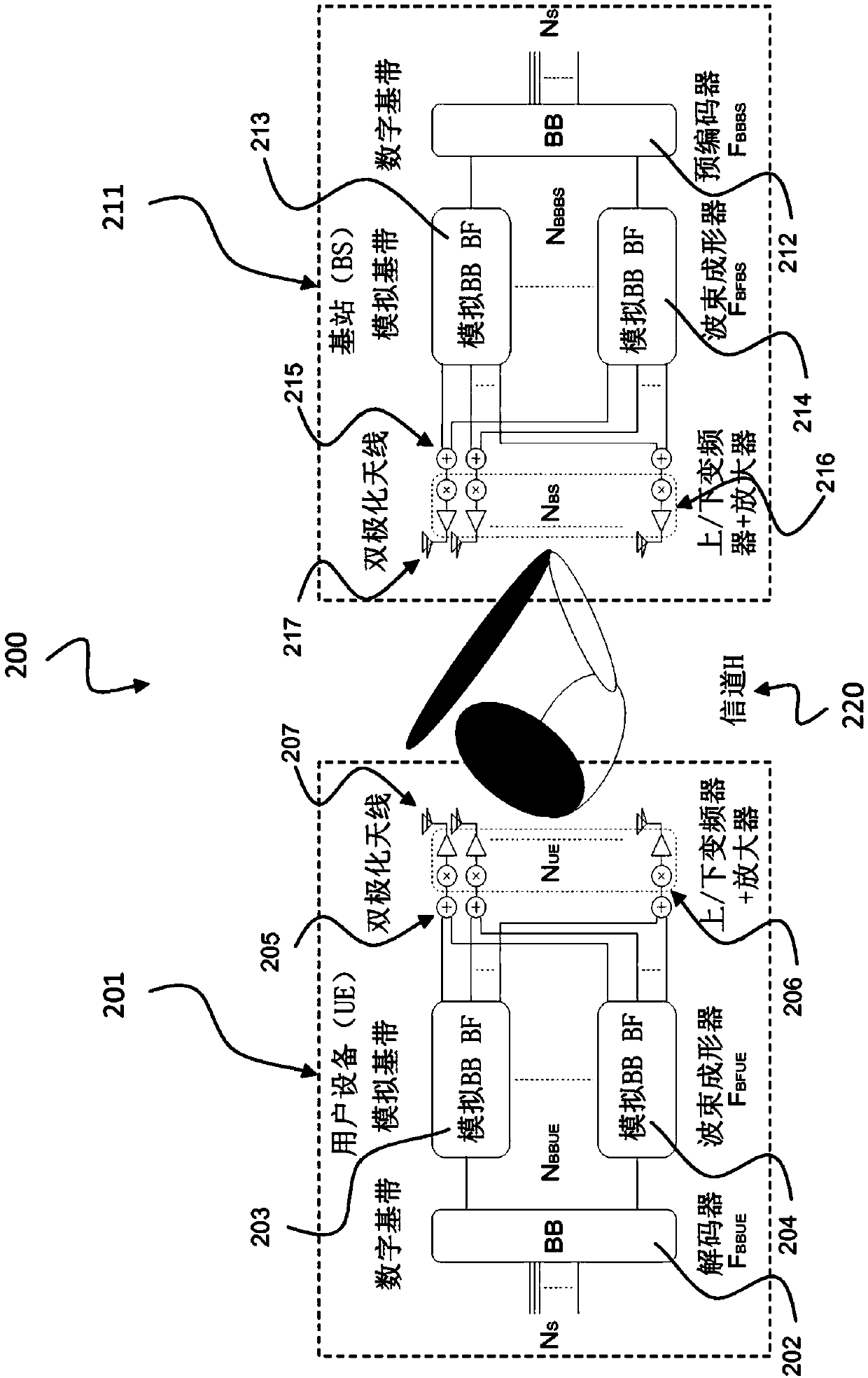
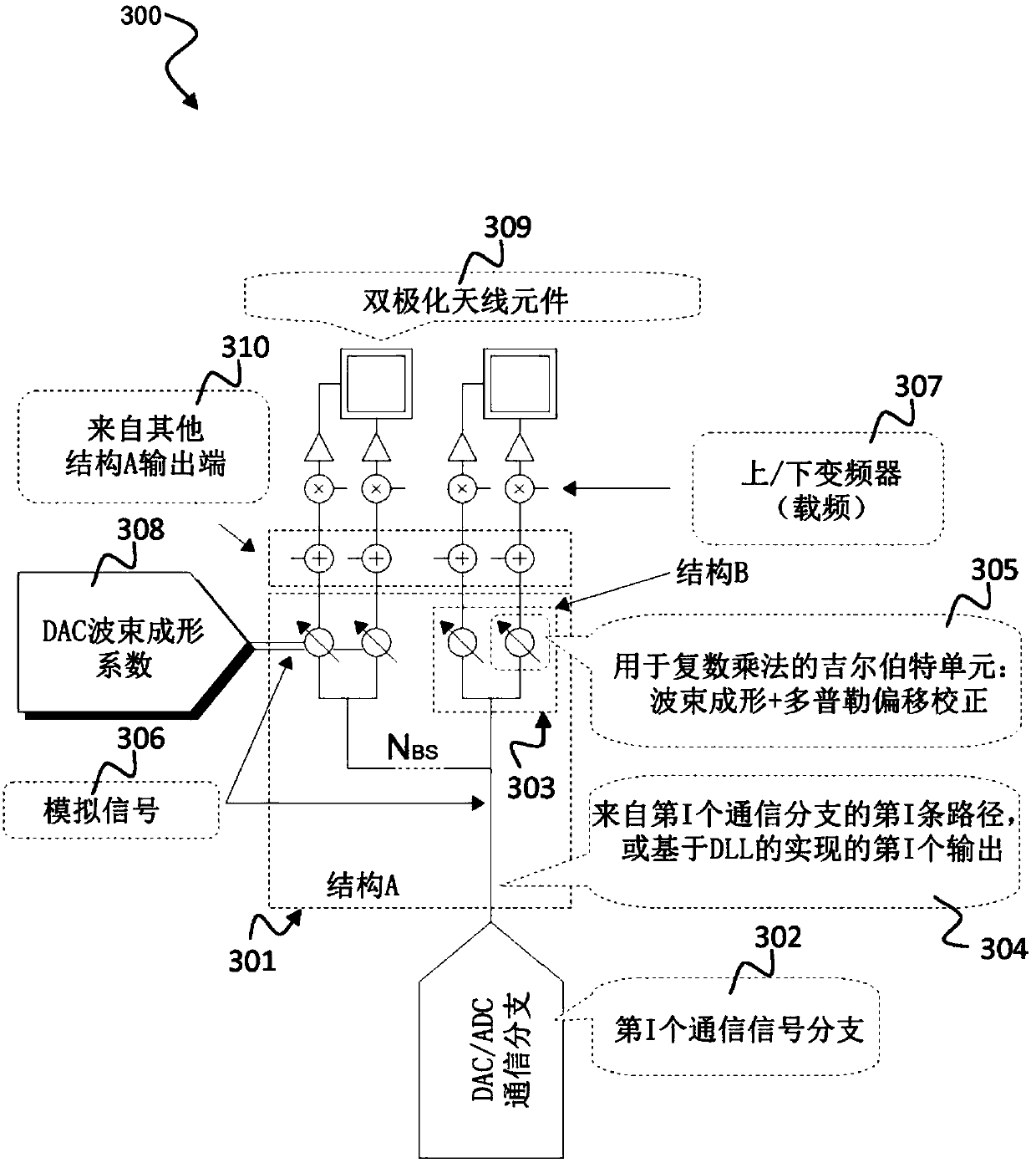
An analog beamforming transmitter includes: a plurality of beamforming transmission circuits coupled in parallel between a signal input and an array of antenna ports, wherein the signal input is configured to receive an analog complex-valued communication signal having an in-phase and a quadrature component, wherein each antenna port of the array of antenna ports is configured to provide a dual-polarized antenna signal having a first polarization component and a second polarization component, wherein each beamforming transmission circuit is coupled between the signal input and a respective antenna port of the array of antenna ports, wherein each beamforming transmission circuit comprises a first coefficient input for receiving a first analog complex-valued beamforming coefficient a set offirst analog complex-valued beamforming coefficients and a second coefficient input for receiving a second analog complex-valued beamforming coefficient of a set of second analog complex-valued beamforming coefficients.

Description

technical field [0001] The present disclosure relates to analog beamforming transmitters and analog beamforming receivers. The present disclosure also relates to analog polarization adjusted transmitters, analog polarization adjusted receivers, analog Doppler shift compensated transmitters, analog Doppler shift compensated receivers, analog delay compensated transmitters, analog delay compensated receivers and Antenna arrangement including signal distribution unit. In particular, the present disclosure relates to beamforming techniques in wireless communication systems and wideband polarization beamforming methods with spatio-temporal processing. Background technique [0002] The propagation characteristics of mmWave are different from the lower frequency bands usually used in communication systems. Its main feature is the "quasi-optical" behavior due to the small wavelength size. As a result, rough surface scattering effects are enhanced, reflections become more specular...

Claims


Application Information

Patent Timeline
Patent Type & Authority Applications(China)
IPC IPC(8): H04B7/06H04B7/00H04B7/01H04B7/08
CPCH04B7/002H04B7/01H04B7/0617H04B7/0671H04B7/0691H04B7/084H04B7/086H04B7/0874H04B7/10
Inventor 罗健雷纳·托梅迭戈·杜普雷施马提亚斯·罗丁施特凡·黑夫纳罗伯托·穆勒克里斯蒂安·施耐德多米尼克·舒尔茨
Owner HUAWEI TECH CO LTD
Learn More