
Traffic light recognition device and traffic light recognition method

A recognition device and signal machine technology, applied in the direction of control devices, character and pattern recognition, image communication, etc., can solve the problems of image blur, confusion, difficult image recognition, etc.

Active Publication Date: 2018-03-27
NISSAN MOTOR CO LTD
View PDF7 Cites 1 Cited by
  • Summary
  • Abstract
  • Description
  • Claims
  • Application Information

AI Technical Summary

Problems solved by technology

[0007] However, in the conventional example disclosed in Patent Document 1, while changing the imaging direction of the camera, the image captured by the camera is blurred (confused), making it difficult to perform image recognition.
As a result, while changing the imaging direction of the camera, the detection accuracy of the lighting state of the traffic signal may decrease.

Method used


Image

  • Traffic light recognition device and traffic light recognition method
  • Traffic light recognition device and traffic light recognition method
  • Traffic light recognition device and traffic light recognition method

Examples


Embodiment Construction

[0029] Hereinafter, embodiments of the present invention will be described with reference to the drawings.

[0030] [Description of the first embodiment]

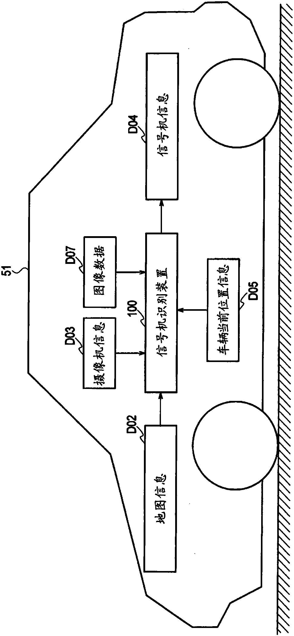
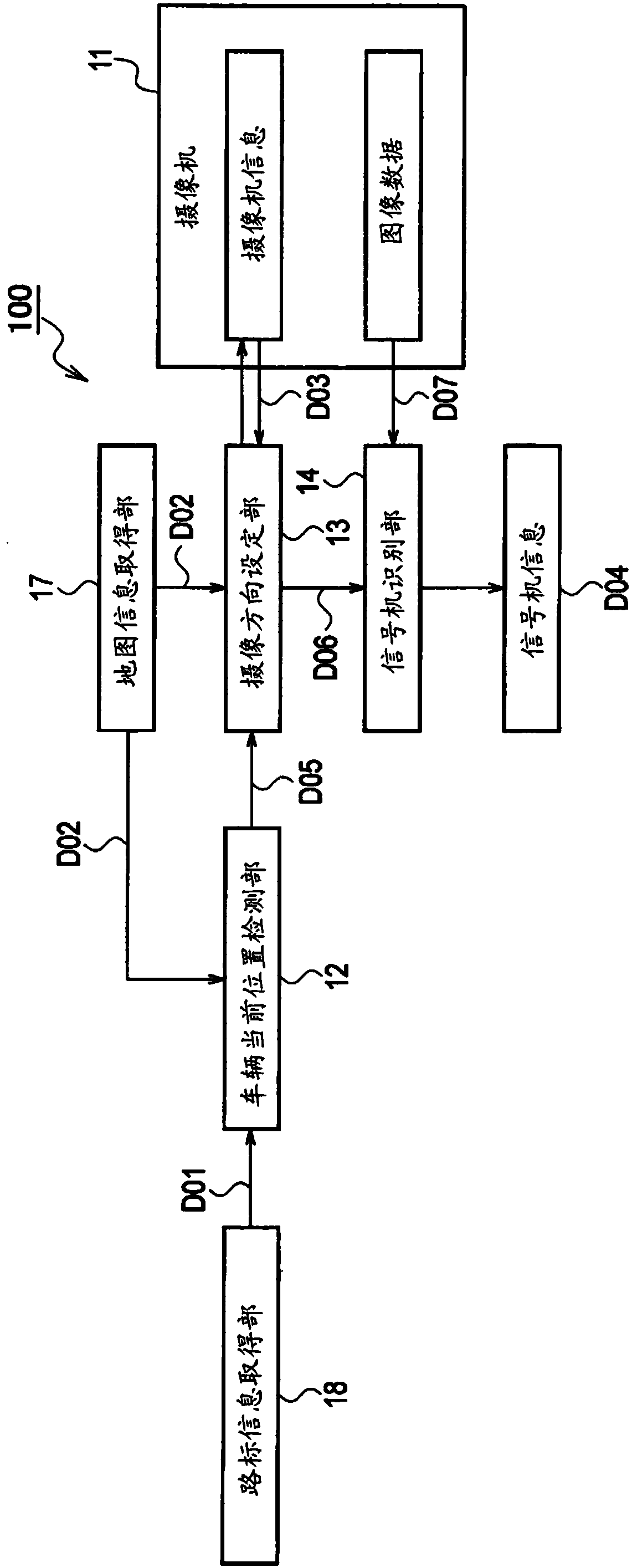
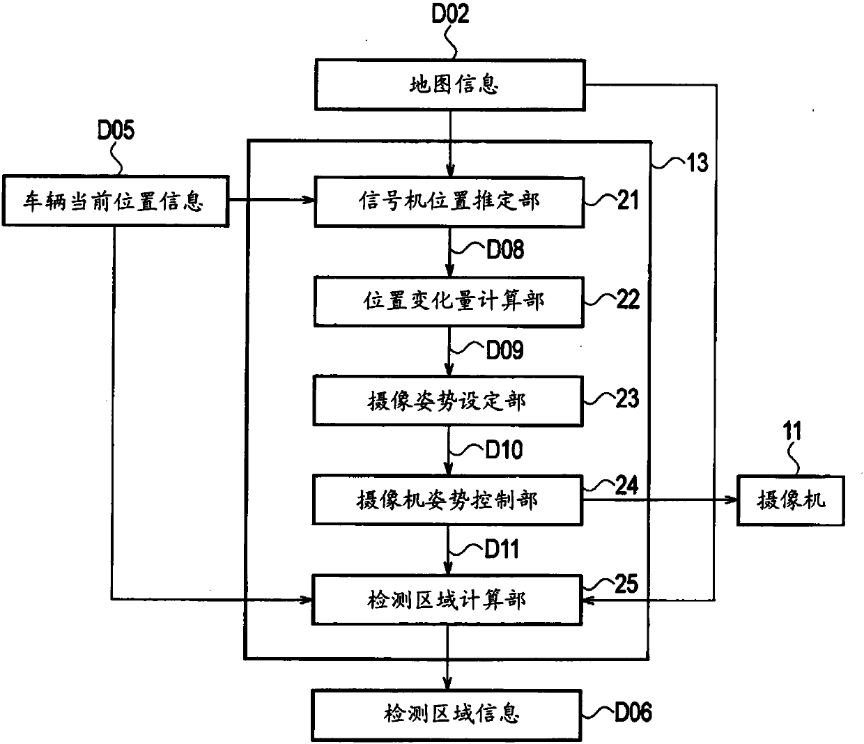
[0031] figure 1 It is a block diagram showing the configuration of the traffic signal identification device and its peripheral devices according to the first embodiment of the present invention. in addition, figure 2 is detailed figure 1 A block diagram of the signal identification device 100 is shown. Such as figure 1 As shown, the traffic signal recognition device 100 is mounted on a vehicle 51 , and map information D02 , camera information D03 , vehicle current position information D05 , and image data D07 are input from various devices mounted on the vehicle 51 . And the signal information D04 which is the information recognized by this signal recognition apparatus 100 is output to the following apparatus.

[0032] The camera information D03 is related to the camera 11 (refer to figure 2 ) information on the in...


PUM


Abstract

A traffic light recognition device is provided with a camera (11) that captures an image of the vicinity of a vehicle, a map information acquisition unit (17) that acquires map information for the vicinity of the vehicle, a current vehicle position detection unit (12) that detects the current position of the vehicle on a map, and a traffic light position estimation unit (21) that estimates the position of the traffic light in the image on the basis of the current vehicle position and the map information. The traffic light recognition device is additionally provided with an imaging orientationsetting unit (23) that sets the imaging direction of the camera on the basis of the position of the traffic light in the image and the future direction of movement of the traffic light in the image, acamera orientation control unit (24) that changes the imaging direction of the camera to an imaging direction set by an imaging direction setting unit, and a traffic light recognition unit (14) thatrecognizes the traffic light from the image captured by the camera in the imaging direction. The present invention makes it possible to highly accurately detect the lighting state of a traffic light without being affected by the orientation of a camera.

Description

technical field [0001] The present invention relates to a signal recognition device and a signal recognition method mounted on a vehicle to recognize a signal. Background technique [0002] For example, in a vehicle equipped with an automatic driving function, driving such as stopping and driving is controlled by recognizing a signal provided on the driving route of the vehicle and detecting the lighting state such as the lighting color of the signal. [0003] As a conventional traffic signal identification device, for example, a device disclosed in Patent Document 1 (JP Unexamined Patent Application Publication No. 11-306489) is known. In Cited Document 1, a camera is mounted on a vehicle to photograph a traffic signal ahead. At this time, the angle of the horizontal direction and the angle of the vertical direction of the camera are controlled so that the traffic signal is positioned at the center of the image captured by the camera. Then, the enlargement ratio is contro...

Claims


Application Information

Patent Timeline
IPC IPC(8): G08G1/16H04N5/225
CPCG08G1/09623G06V20/584H04N23/00G08G1/16G08G1/0967G06F18/00B60W2555/60G06V20/582B60R11/04G06T2207/30256
Inventor 山井大贵松尾治夫冲孝彦铃木章
Owner NISSAN MOTOR CO LTD
Learn More