
Two-degree-of-freedom high-speed carrying and moving mechanism

A degree of freedom, high-speed technology, applied in the directions of manipulators, conveyor objects, transportation and packaging, can solve the problems of insufficient longitudinal stiffness and insufficient stability, and achieve the effects of good longitudinal stiffness, simple structure and improved stability.

Pending Publication Date: 2018-03-27
SHANDONG UNIV OF SCI & TECH
View PDF9 Cites 0 Cited by
  • Summary
  • Abstract
  • Description
  • Claims
  • Application Information

AI Technical Summary

Problems solved by technology

Although this patent can realize two-degree-of-freedom translation, it has only two branch chains, which is not stable enough, and its longitudinal rigidity is insufficient when moving at high speed

Method used


Image

  • Two-degree-of-freedom high-speed carrying and moving mechanism
  • Two-degree-of-freedom high-speed carrying and moving mechanism
  • Two-degree-of-freedom high-speed carrying and moving mechanism

Examples


Embodiment 1

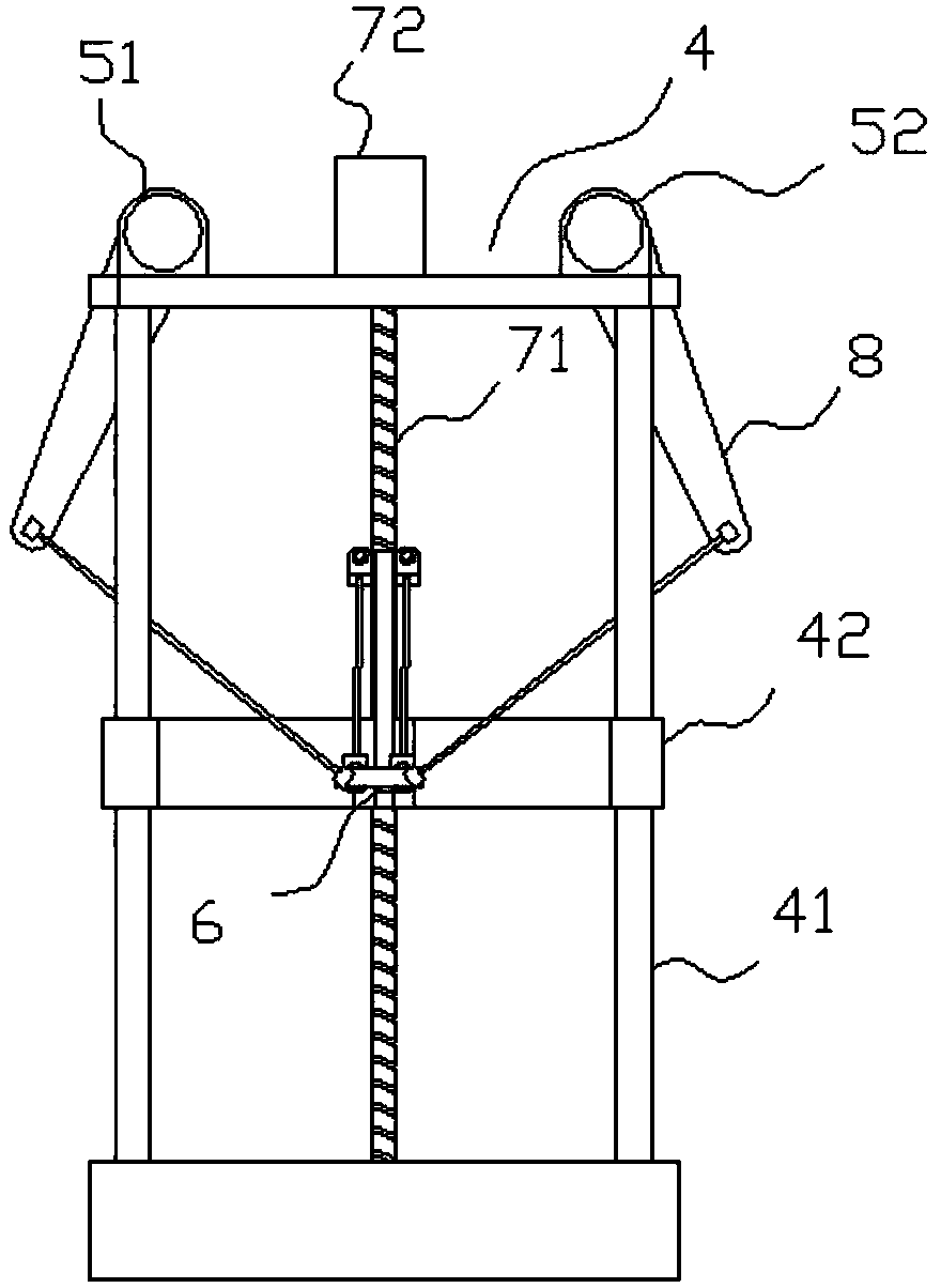
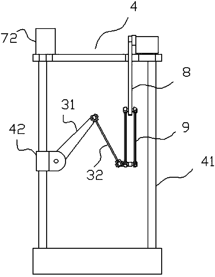
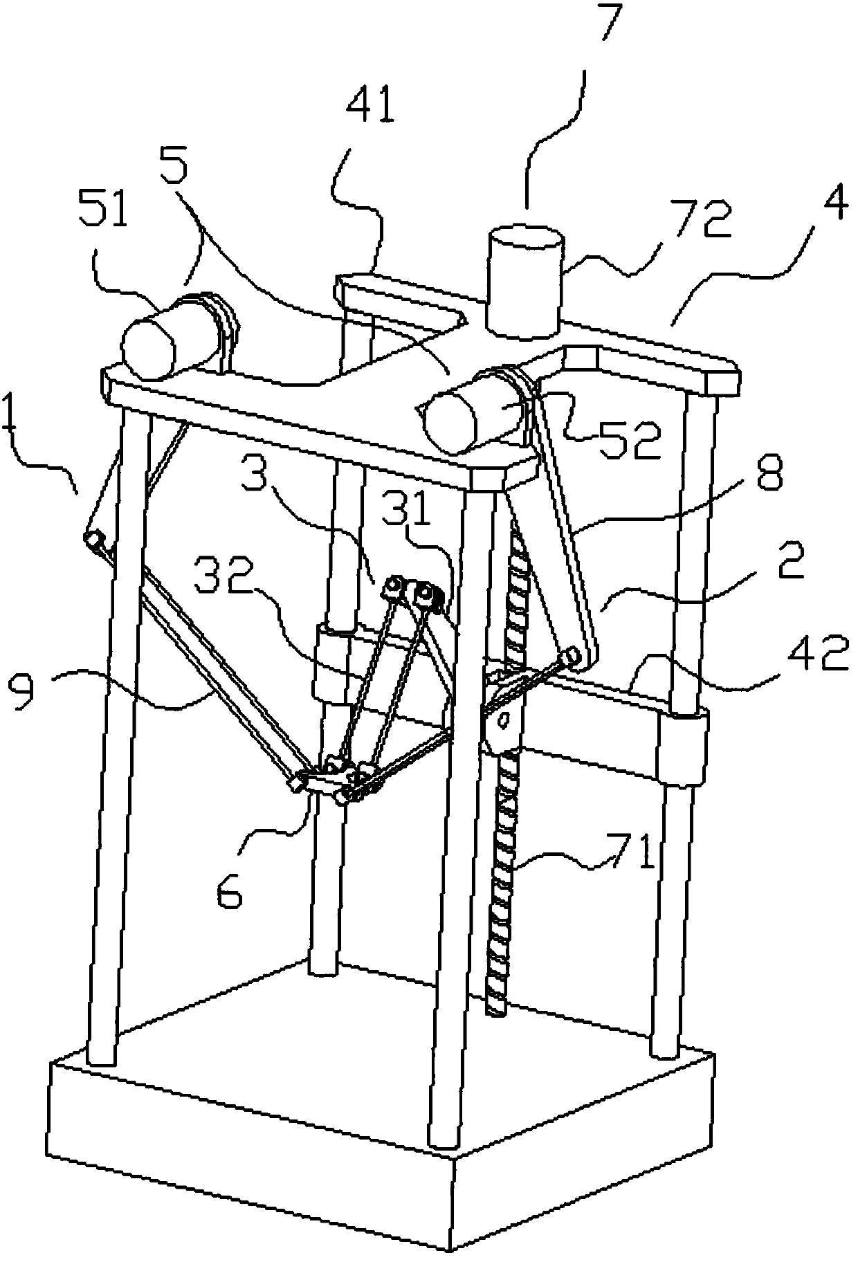
[0028] Such as Figure 1 to Figure 4 As shown, a two-degree-of-freedom high-speed transport and displacement mechanism includes a frame 4, a first branch chain 1, a second branch chain 2, a third branch chain 3, a moving platform 6 and a power unit 5; preferably, the The frame 4 includes a fixed bracket 41 , a movable bracket 42 slidably mounted on the fixed bracket 41 , and a lead screw drive mechanism 7 that drives the movable bracket 42 to slide relative to the fixed bracket 41 . The movable bracket 42 is configured to slide up and down along the fixed bracket 41. The screw drive mechanism 7 includes a screw 71 that is rotatably connected to the fixed bracket 41 at both ends, and a screw drive is provided at one end of the screw 71. The motor 72 , the lead screw 71 runs through the movable bracket 42 , and when the lead screw 71 rotates, the movable bracket 42 moves axially along the lead screw 71 . The first branch chain 1 and the second branch chain 2 are installed on a ...

Embodiment 2

[0038] Such as Figure 5As shown, this embodiment is a further improvement on the basis of Embodiment 1. The specific difference is that the third branch chain 3 is equipped with a power device, which is a third power device 53, and the third power device 53 is fixed on On the movable support 42, its output shaft is connected with the boom 31 of the third branch chain 3 to drive the boom 31 to rotate. When the first branch chain 1 and / or the second branch chain 2 drive the moving platform 6 to move, the third branch chain 1 The power device 53 drives the third branch chain 3 to actively follow the movement of the moving platform 6 . By configuring the driving device on the third branch chain 3, the entire mechanism becomes a redundant drive parallel mechanism, that is, a parallel mechanism with more input components than output components. Compared with ordinary parallel mechanisms, it has higher rigidity and force operation performance. Excellent, large carrying capacity and...

Embodiment 3

[0040] Such as Image 6 As shown, the difference between this embodiment and Embodiment 1 is that the boom 31 is configured to move in a third motion plane, and the third motion plane is set parallel to the horizontal plane. Correspondingly, the large arm 31 of the third branch chain 3 The arm 31 swings in the horizontal direction, and the first movement plane and the third movement plane perpendicularly intersect. The boom 31 is arranged in the third motion plane, which can have different working spaces and improve applicability.


PUM


Abstract

The invention relates to a two-degree-of-freedom high-speed carrying and moving mechanism. The two-degree-of-freedom high-speed carrying and moving mechanism comprises a rack, a first branched chain,a second branched chain and a moving platform, wherein the first branched chain and the second branched chain are installed on the rack, and the moving platform is rotationally connected with the first branched chain and the second branched chain. The first branched chain and the second branched chain are each provided with a power device, and the moving plane of the first branched chain and the moving plane of the second branched chain are the same plane or two parallel planes. The two-degree-of-freedom high-speed carrying and moving mechanism further comprises a third branched chain installed on the rack, the moving plane of the third branched chain is inclined relative to the moving plane of the first branched chain or is perpendicular to the moving plane of the first branched chain, and the third branched chain is rotationally connected with the moving platform. The two-degree-of-freedom high-speed carrying and moving mechanism is simple in structure, easy to assemble and good in bearing capacity; and the third branched chain is used as a restraining branched chain, so that rotation of the moving platform is avoided, and the stability of the moving platform is improved.

Description

technical field [0001] The invention relates to the field of industrial manipulators, in particular to a two-degree-of-freedom high-speed transport and displacement mechanism. Background technique [0002] With the development of my country's economy, high-speed handling mechanisms are becoming more and more important in production applications. They can replace human labor in many industrial fields and realize production automation. The use of high-speed handling mechanism can not only reduce human physical labor and waste of human resources, but also effectively improve work efficiency. The automatic production lines in food, electronics, light industry, medicine and other industries often involve the handling of small and light products such as biscuits and resin lenses between two points. This kind of handling generally requires extremely high The speed is in line with the beat of the production line. Existing light-load handling mechanisms are mainly divided into two ...

Claims


Application Information

Patent Timeline
Patent Type & Authority Applications(China)
IPC IPC(8): B25J9/00B65G47/74
CPCB65G47/74B25J9/003
Inventor 陈修龙李跃文陈天祥
Owner SHANDONG UNIV OF SCI & TECH
Learn More