Screw blade cleaning device of building screw feeding machine

The technology of screw feeder and screw blade is applied in the field of construction screw feeder screw blade cleaning device and screw cleaning device, which can solve the problems of destroying the surface flatness, affecting the conveying efficiency, low efficiency, etc., so as to reduce wear and improve cleaning. The effect of efficiency

Active Publication Date: 2018-03-27
徐州华显凯星信息科技有限公司
View PDF8 Cites 3 Cited by
  • Summary
  • Abstract
  • Description
  • Claims
  • Application Information

AI Technical Summary

Problems solved by technology

[0002] At present, in the process of building construction, screw feeders are mostly used for the transportation of concrete and sand and gravel for building construction, and the materials are conveyed forward through the rotation of the screw blades. During long-term use, the outer surface of the screw blades will adhere to The material is prone to the shaft-holding phenomenon of the material, which reduces the material conveying section, affects the conveying efficiency, and causes the spiral blade to rotate unbalanced and vibrate. Therefore, the spiral blade needs to be cleaned regularly. When cleaning the spiral blade, kerosene , gasoline, and diesel as cleaning agents, put the spiral blades into an oil basin with a mesh screen, scrub with a wire brush, the oil will sink into the bottom of the basin through the mesh screen, and the cleaned spiral blades can be dried in the air. Prepare kerosene, gasoline and other cleaning agents on site. Kerosene and gasoline are flammable items, which are extremely dangerous on site. When cleaning the surface, use a wire brush to scrub the surface, which will damage the smoothness of the surface and form furrows on the surface of the spiral blade. , so that when the screw blade is transported, the material is further attached to the surface, and it needs to be dried after cleaning. The whole process takes a long time and the efficiency is low, which affects the use of the screw feeder. When cleaning the outer edge of the screw blade, due to the thin wall, Mistakes later in the cleaning process can cause gaps in the edges, causing material to accumulate in the gaps during the transfer process, affecting the work of the bolt feeder
[0003] Publication number CN204453617U discloses a self-cleaning screw conveyor. One or more pairs of screw shafts are arranged in the housing. The driving screw shaft is installed at the center of the driving egg gear, and the driven screw shaft is installed at the center of the driven egg gear. position, when the main and driven oval gears mesh, the center distance between the main and driven helical shafts remains unchanged, the pitch of the helical blades on the two helical shafts in each pair of helical shafts is the same, and the direction of rotation is opposite, and the distance between the two helical shafts The distance between the axes is smaller than the diameter of the helical blades. The self-cleaning screw conveyor of the present invention includes one or more pairs of helical shafts, which are used in pairs and are synchronously driven by oval gears. When working, the two helical shafts rotate in opposite directions , and the rotation speed ratio presents a periodic change, so that the helical blades of the two helical shafts produce relative displacement in the direction of the shaft length. This method increases the number of rotating shafts in the bolt feeder, and cleans through the cooperation between the oval gears. The equipment structure is complicated , The oval gear is easy to get stuck when it is matched, which affects the operation of the equipment and makes it difficult to maintain later

Method used


Image

  • Screw blade cleaning device of building screw feeding machine

Examples


Embodiment Construction

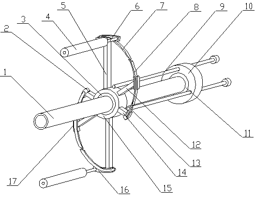
[0023]A spiral blade cleaning device for a construction screw feeder of the present invention is realized in the following way: when in use, the spiral blade is fixed, the screw rod (1) is inserted into the middle of the spiral blade, and the clamping rollers (4) on both sides are respectively mixed with the spiral blade Fix the upper stator of the outer rotor motor (10), and then start the outer rotor motor (10). When rotating, the first cleaning arm (5) first contacts the spiral blade, and drives the fixing ring through the guide rod (9) (15) rotates, the fixed ring (15) drives the screw sleeve (3) to rotate along the screw rod (1), and the screw sleeve (3) moves along the screw rod (1), so that the first cleaning arm on the fixed ring (15) ( 5), the second cleaning arm (12), the third cleaning arm (14) rotate and move, and the surface of the spiral blade is attached, and the first cleaning knife (7) on the first cleaning arm (5) rotates to the outside of the spiral blade Th...


PUM


Abstract

The invention relates to a screw blade cleaning device of a building screw feeding machine, and discloses a device which is used for clamping and fixing outer edges of dismounted screw blades, and then conducting screw cleaning through attachment of cleaning arms and the surfaces of the screw blades. The screw blade cleaning device is characterized in that an outer robot motor is arranged at one end of a screw through a connecting sleeve, a plurality of through holes are formed in a rotor of the outer robot motor, a screw sleeve is arranged on the screw in a sleeving manner, and a fixing ringsleeve is arranged on the screw sleeve; one ends of a plurality of guide rods correspondingly penetrate the outer robot motor to be fixed to a fixing ring, spring pipes are arranged at the middle portions of the guide rods, the two ends of each guide rod are thin and long round rods, one ends of the two first cleaning arms are vertically arranged on the outer wall of the fixing ring, and the two first cleaning arms are distributed in a 180-degree manner; roots of the first cleaning arms are located at one end of the fixing ring, one ends of two third cleaning arms are vertically arranged on the outer wall of the fixing ring, an included angle between the two second cleaning arms is 180 degrees, and the included angles between the third cleaning arms and the first cleaning arms are 60 degrees.

Description

technical field [0001] The invention relates to a spiral blade cleaning device of a building screw feeder, which relates to a device for cleaning the screw blades on the screw feeder after the screw feeder is maintained during building construction, and belongs to the field of building construction. In particular, it relates to a device for clamping and fixing the outer edge of a disassembled spiral blade, and then cleaning the spiral through the cleaning arm and the surface of the spiral blade. Background technique [0002] At present, in the process of building construction, screw feeders are mostly used for the transportation of concrete and sand and gravel for building construction, and the materials are conveyed forward through the rotation of the screw blades. During long-term use, the outer surface of the screw blades will adhere to The material is prone to the shaft-holding phenomenon of the material, which reduces the material conveying section, affects the conveyin...

Claims


Application Information

Patent Timeline
IPC IPC(8): B08B1/04B08B1/00
CPCB08B1/165B08B1/32
Inventor 不公告发明人
Owner 徐州华显凯星信息科技有限公司
Why Eureka
Try Eureka