
Battery charging detection and timing control system

A timing control, battery charging technology, applied in battery circuit devices, current collectors, electric vehicles, etc., can solve the problems of inconvenient charging and inability to protect electronic products, and achieve the effect of effective protection

Inactive Publication Date: 2018-03-23
四川新驱科为科技有限公司
View PDF0 Cites 0 Cited by
  • Summary
  • Abstract
  • Description
  • Claims
  • Application Information

AI Technical Summary

Problems solved by technology

In the traditional technology, when using an external power supply to charge portable electronic products, in order to avoid overcharging or undercharging, human intervention in the charging process is required, which brings inconvenience to the charging process, and the charging process cannot protect the electronic products well.

Method used


Image

  • Battery charging detection and timing control system

Examples


Embodiment

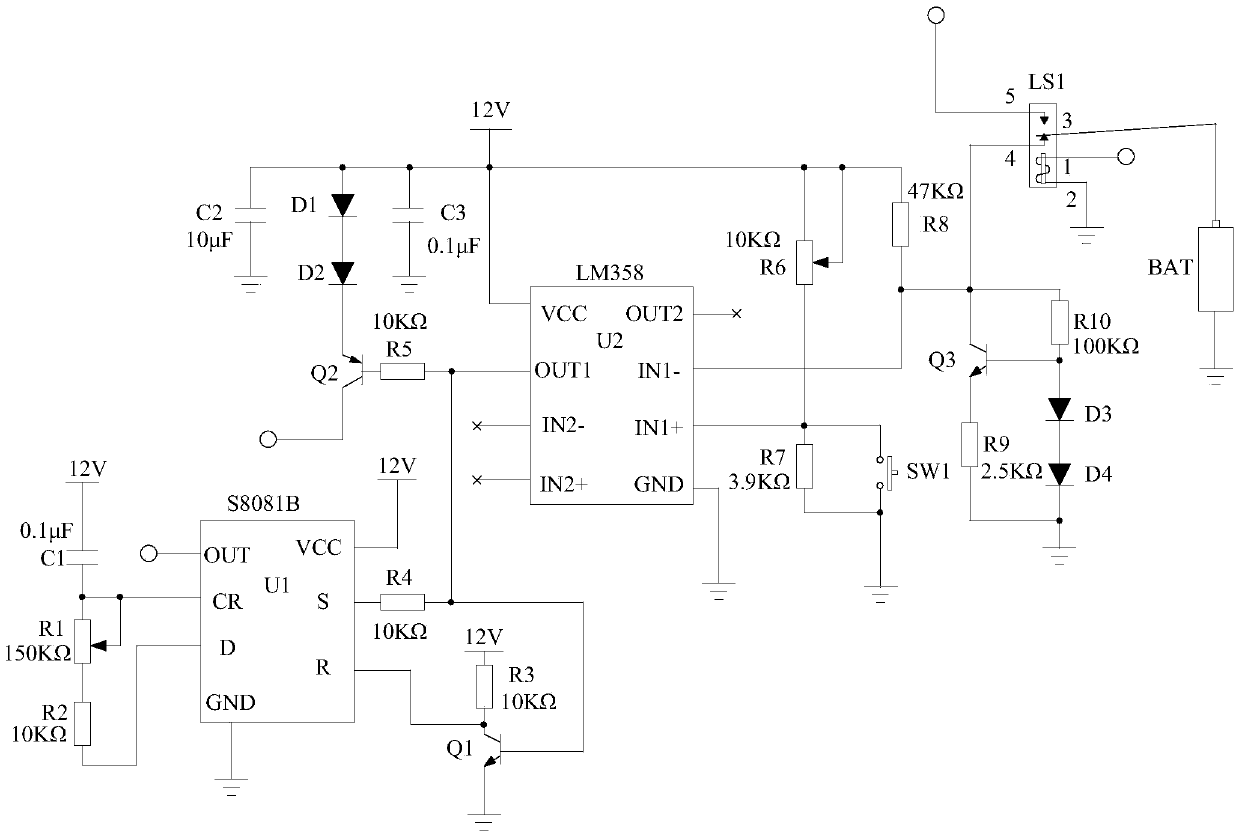
[0015] Such as figure 1 As shown, the battery charging detection timing control system of the present invention includes a relay LS1, a battery BAT connected to the 3-terminal of the relay LS1, a discharge circuit connected to the 4-terminal of the relay LS1, and a detection control circuit connected to the discharge circuit.

[0016] Specifically, the detection control circuit is also connected to terminal 1 of the relay LS1, terminal 2 of the relay LS1 is grounded, and terminal 5 of the relay LS1 is connected to the voltage output terminal of the charging module outside the system. The detection control circuit controls the on and off of the relay LS1 according to the voltage output by the discharge circuit, so as to automatically control the charging of the storage battery BAT.

[0017] Wherein, the discharge circuit includes a transistor Q3, a resistor R9, a resistor R10, a diode D3 and a diode D4. Specifically, the resistor R10 is connected in series between the collecto...


PUM


Abstract

The invention discloses a battery charging detection timing control system, which is characterized in that it includes a relay LS1, a storage battery BAT connected to 3 terminals of the relay LS1, a discharge circuit connected to 4 terminals of the relay LS1, and a detection circuit connected to the discharge circuit. Control circuit; the detection control circuit is also connected to terminal 1 of the relay LS1, and terminal 2 of the relay LS1 is grounded, and the detection control circuit controls the on and off of the relay LS1 according to the voltage output by the discharge circuit. The invention automatically controls the on and off of the relay by detecting the electric quantity of the storage battery, thereby controlling the charging of the storage battery without human intervention in the charging process.

Description

technical field [0001] The invention relates to a control system, in particular to a battery charging detection timing control system. Background technique [0002] Along with the continuous development of electronic technology, portable electronic product has been more and more subject to people's favor. The biggest feature of portable electronic products is that they can be separated from the external power supply within a certain period of time, and only rely on their internal independent energy supply system to work normally, so as to realize the function of freely moving the working place at any time. Therefore, using an external power source to charge its internal battery has become a very critical technical link in a portable electronic system. In the traditional technology, when using an external power supply to charge portable electronic products, in order to avoid overcharging or undercharging, human intervention in the charging process is required, which brings i...

Claims


Application Information

Patent Timeline
Patent Type & Authority Applications(China)
IPC IPC(8): H02J7/00
CPCH02J7/0086
Inventor 王前明
Owner 四川新驱科为科技有限公司
Learn More