
Electric multi-locking switch room chassis device

A switch room and chassis vehicle technology, applied in switchgear, switchgear parts, electrical components, etc., can solve the problem that the reliability of the electric operation of the switch room chassis vehicle cannot be guaranteed, the personal safety of operation and maintenance personnel is endangered, and the electric control logic is imperfect. and other problems, so as to avoid imperfect logic, easy operation and ensure personal safety.

Active Publication Date: 2018-03-23
GUANGDONG MINGYANG ELECTRIC CO LTD
View PDF19 Cites 2 Cited by
  • Summary
  • Abstract
  • Description
  • Claims
  • Application Information

AI Technical Summary

Problems solved by technology

[0002] In the electrical field, with the development of intelligent switch cabinets, electric chassis vehicles are also widely used. Electric chassis vehicles are generally loaded with electrical components used to connect high-voltage lines, so they need to have a higher level of protection and safety. The previous switch room chassis Vehicle device, the electric control logic between each switch is not perfect, there is a situation where any one or two switches are closed to allow the chassis vehicle control module to control the operation of the chassis vehicle, and the reliability of the electric operation of the chassis vehicle in the switch room cannot be guaranteed; in addition, There is no reliable locking between manual operation and electric operation, which is very prone to misoperation and even endangers the personal safety of operation and maintenance personnel

Method used


Image

  • Electric multi-locking switch room chassis device
  • Electric multi-locking switch room chassis device
  • Electric multi-locking switch room chassis device

Examples


Embodiment Construction

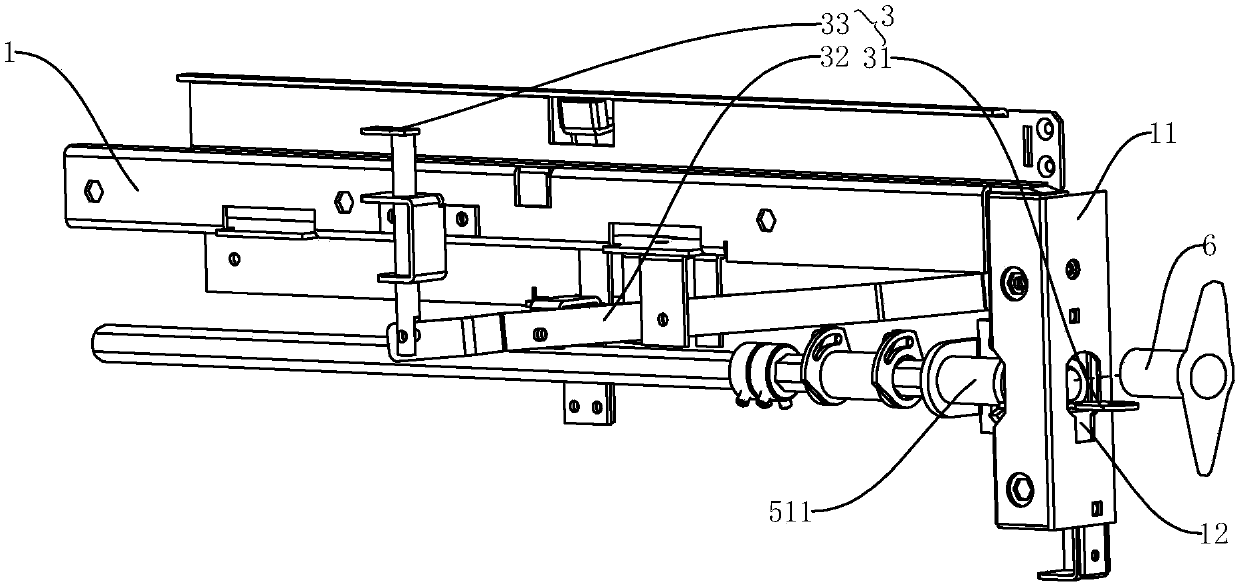
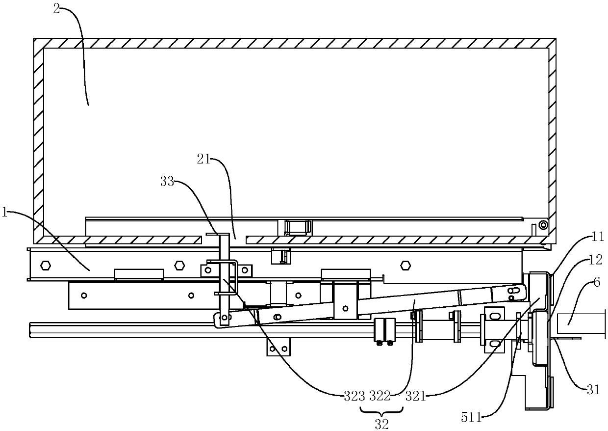
[0026] like Figure 1-Figure 5 As shown, the electric chassis vehicle of the present invention is arranged in the switch chamber and is movably connected with the switch chamber housing 1. Here, a guide rail cooperating with the electric chassis vehicle is arranged in the general switch chamber, and the chassis vehicle 2 can move along the guide rail.

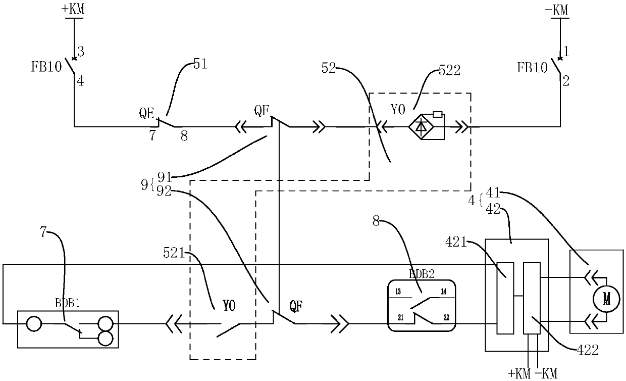
[0027] This design comprises ground knife switch part 51, electromagnetic lock part 52 and circuit breaker part 9, and electromagnetic lock part 52 comprises electromagnetic lock switch 521 and the electromagnetic lock coil 522 of control electromagnetic lock switch 521 on-off, ground knife switch part 51 and external The power supply module and the electromagnetic lock coil 522 are electrically connected to supply power for the electromagnetic lock coil 522 by the power supply module;

[0028] The circuit breaker part 9 comprises a first circuit breaker switch 91 and a second circuit breaker switch 92, the first circuit breake...


PUM


Abstract

The invention discloses an electrical multi-locking switch chamber chassis device, comprising a ground knife switch part, a circuit breaker part and an electromagnetic lock part. The electromagnetic lock part comprises an electromagnetic lock switch and an electromagnetic lock coil for controlling the on / off of the electromagnetic lock switch. The ground knife switch part is electrically connectedwith an external power supply module and the electromagnetic lock coil separately to supply power from the power supply module to the electromagnetic lock coil. The circuit breaker part includes a first circuit breaker switch and a second circuit breaker switch. The first circuit breaker switch is connected in series with the ground knife switch part. The second circuit breaker switch is connected in series with the electromagnetic lock switch to form a series circuit, and the series circuit is electrically connected with a chassis control module to provide the chassis control module with a closing judgment signal to control the operation of a chassis. The design has the characteristics of clear control logic and easy operation and achieves the multi-protection of the chassis electricallyat the same time to prevent injury to on-site personnel.

Description

technical field [0001] The invention relates to electrical equipment, in particular to an electric multiple locking switch room chassis vehicle device. Background technique [0002] In the electrical field, with the development of intelligent switch cabinets, electric chassis vehicles are also widely used. Electric chassis vehicles are generally loaded with electrical components used to connect high-voltage lines, so they need to have a higher level of protection and safety. The previous switch room chassis Vehicle device, the electric control logic between each switch is not perfect, there is a situation where any one or two switches are closed to allow the chassis vehicle control module to control the operation of the chassis vehicle, and the reliability of the electric operation of the chassis vehicle in the switch room cannot be guaranteed; in addition, There is no reliable locking between manual operation and electric operation, which is very prone to misoperation and e...

Claims


Application Information

Patent Timeline
Patent Type & Authority Applications(China)
IPC IPC(8): H02B11/167H02B11/04H02B11/133H02B11/02
CPCH02B11/02H02B11/04H02B11/133H02B11/167Y02T10/70
Inventor 袁红珍戴国权陈立岳丕榜
Owner GUANGDONG MINGYANG ELECTRIC CO LTD
Learn More