
a led light bulb

A technology of LED bulbs and LED light sources, applied in the field of lighting, can solve the problems of high production cost, low production efficiency, large light decay, etc., and achieve the effects of convenient and fast installation, preventing heat accumulation, and increasing aesthetics.

Active Publication Date: 2020-07-10
FOSHAN ELECTRICAL & LIGHTING
View PDF8 Cites 0 Cited by
  • Summary
  • Abstract
  • Description
  • Claims
  • Application Information

AI Technical Summary

Problems solved by technology

[0002] LED filament bulbs are widely used in the market due to their energy saving, environmental protection, long life and other characteristics. At present, the power supply of commonly used LED filament bulbs is installed inside the lamp holder to ensure that the LED bulbs can work normally. During the assembly process, the light source needs to be installed first. Extend into the inside of the bulb, and then seal the bulb so that the sealed bulb matches the lamp cap, which facilitates the connection between the bulb and the lamp cap, then puts the power supply in the inner cavity of the lamp cap, and finally connects the cap with the cap. The process of this assembly method is cumbersome, the production efficiency is low, and the production cost is high
On the other hand, the cost of the LED filament itself is relatively high. SMD lamp beads are used and sealed in the bulb. Both contain solder and PCB boards. Solder and PCB boards contain organic volatile substances, which are easy to accumulate inside the closed bulb. Organic volatile substances, organic volatile substances will pollute the LED lamp bead when the lamp is turned on at high temperature, causing the LED lamp bead to turn black, resulting in relatively large light decay and reducing the service life of the LED bulb. Therefore, it is necessary to propose a A new type of LED light bulb solves the above problems

Method used


Image

  • a led light bulb
  • a led light bulb

Examples


Embodiment Construction

[0024] In order to enable those skilled in the art to better understand the technical solutions of the present invention, the present invention will be further described in detail below in conjunction with the accompanying drawings and preferred embodiments.

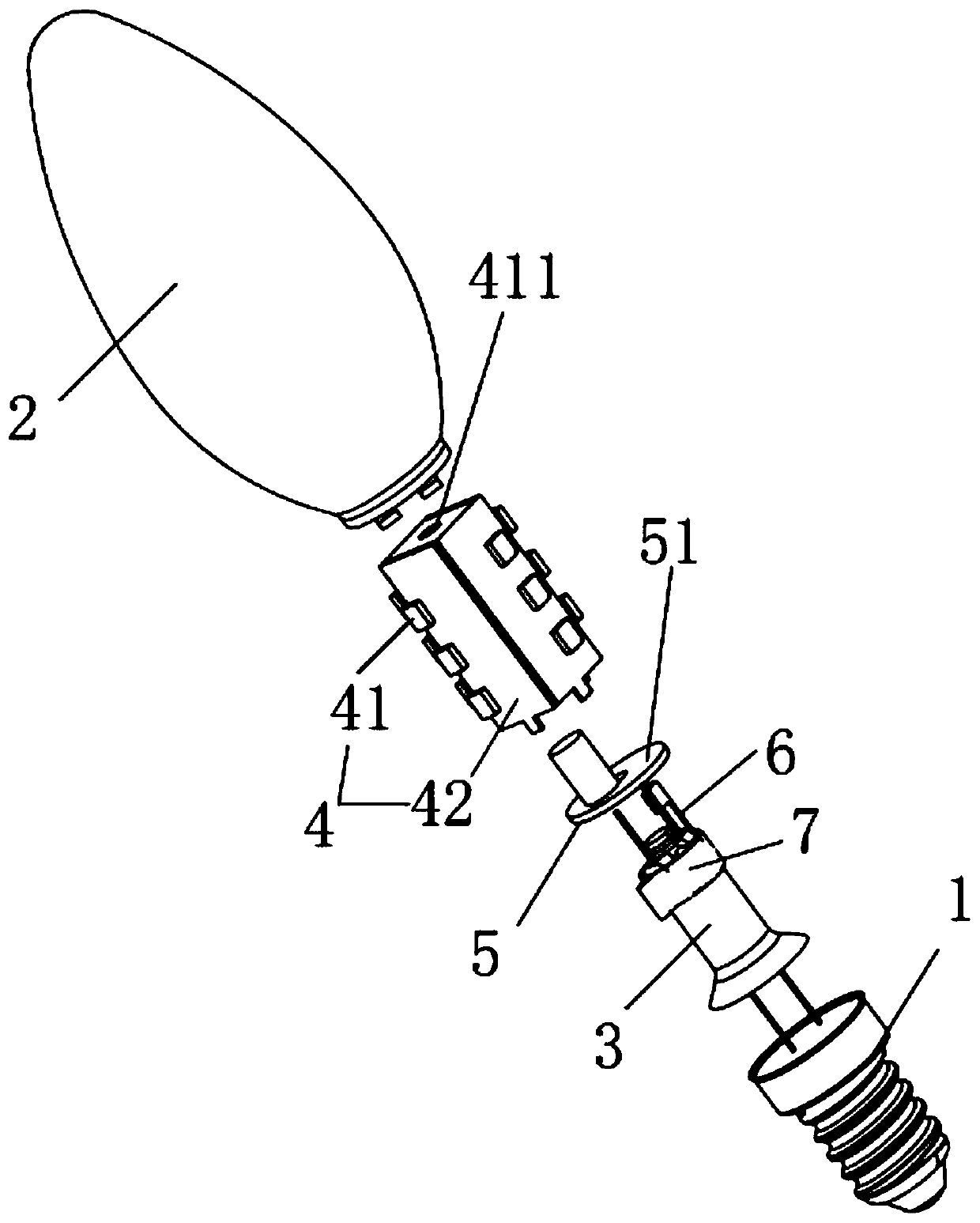
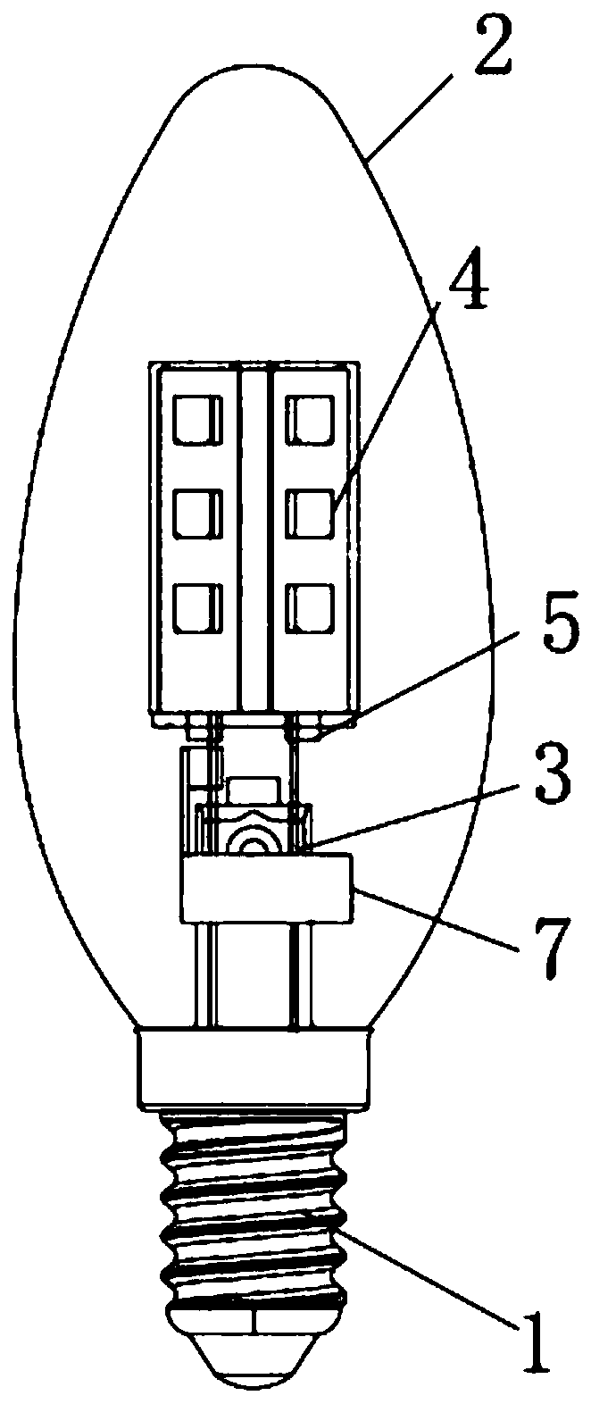
[0025] Such as Figure 1-2 As shown, an LED light bulb includes a lamp cap 1, a bulb shell 2 connected to the lamp cap 1, a stem 3 extending into the bulb shell 2, an LED light source 4 located in the bulb shell 2, and The LED light source 4 is connected to a power supply 5 and protective gas; the LED light source 4 is installed on the stem 3, the power supply 5 is installed on the stem 3 and is located inside the bulb 2, so The bulb 2 and the stem 3 form a closed cavity, and the protective gas is located inside the closed cavity, which includes oxygen and helium, wherein the volume of oxygen accounts for 1-50% of the total volume of the protective gas. %.

[0026] The lamp holder 1 is used to realize the mechanical co...


PUM


Abstract

The invention relates to an LED bulb. The LED bulb comprises a lamp holder, a bulb shell, a core column, an LED light source, a power source and protective gas, wherein the bulb shell is connected with the lamp holder; the core column extends into the bulb shell; the LED light source is located inside the bulb shell; and the power source is connected with the LED light source. The LED light sourceis mounted on the core column. The power source is mounted on the core column and located inside the bulb shell. A closed cavity is formed by the bulb shell and the core column. The protective gas islocated inside the closed cavity and comprises oxygen gas and helium gas, wherein the volume of the oxygen gas accounts for 1-50% of the total volume of the protective gas. According to the LED bulb,the connected LED light source, the power source and the core column are extended into the cavity of the bulb shell, and then the bulb shell is sealed; the LED bulb is convenient and fast to mount, high in mechanized production efficiency and low in production cost; and by means of the protective gas, the service life of the LED bulb is prolonged.

Description

technical field [0001] The present invention relates to the technical field of lighting, in particular to an LED light bulb. Background technique [0002] LED filament bulbs are widely used in the market due to their energy saving, environmental protection, long life and other characteristics. At present, the power supply of commonly used LED filament bulbs is installed inside the lamp holder to ensure that the LED bulbs can work normally. During the assembly process, the light source needs to be installed first Extend into the inside of the bulb, and then seal the bulb so that the sealed bulb matches the lamp cap, which facilitates the connection between the bulb and the lamp cap, then puts the power supply in the inner cavity of the lamp cap, and finally connects the cap with the cap. The process of this assembly method is loaded down with trivial details, and production efficiency is low, and production cost is high. On the other hand, the cost of the LED filament itself...

Claims


Application Information

Patent Timeline
Patent Type & Authority Patents(China)
IPC IPC(8): F21K9/232F21K9/238F21V19/00F21V23/00F21V29/83F21Y115/10
CPCF21K9/232F21K9/238F21V19/001F21V23/004F21V29/83F21Y2115/10
Inventor 林庆朱奕光黄付果陈贵琴黄林国
Owner FOSHAN ELECTRICAL & LIGHTING
Learn More