
Device for improving test ability of power capacitor

A technology of power capacitors and experimental capabilities, which is applied in the direction of measuring devices, instruments, and measuring electronics, and can solve problems such as inaccurate product measurement, large product backlog, and low product testing capabilities.

Inactive Publication Date: 2018-03-23
ANHUI JIANGWEI PRECISION IND
View PDF5 Cites 9 Cited by
  • Summary
  • Abstract
  • Description
  • Claims
  • Application Information

AI Technical Summary

Problems solved by technology

[0007] 1 Only a single power capacitor can be tested;
[0008] 2 The contact resistance between the upper electrode of the capacitor and the cable clamp is too large, and the temperature is too high. When measuring the withstand voltage and dielectric loss of the capacitor, the product measurement is inaccurate, and the unqualified product flows into the next process, causing the product to appear during operation. electrical failure or accident;
[0009] 3 The operator is inconvenient to operate, the test ability cannot be improved, and the operator often enters and exits the test area, which will cause harm to the human body due to the action of the electric field;
[0010] 4 Using this method to test the electrical performance of capacitors, the product testing ability is low, and the work efficiency of operators is reduced, resulting in too much product backlog, which cannot meet the subsequent procedures. In order to solve this test bottleneck, how to improve the capacitor testing ability can be effectively It is a technical problem to be solved by those skilled in the art to solve the electrical performance test of a single power capacitor

Method used


Image

  • Device for improving test ability of power capacitor
  • Device for improving test ability of power capacitor
  • Device for improving test ability of power capacitor

Examples


Embodiment Construction

[0025] The following will clearly and completely describe the technical solutions in the embodiments of the present invention with reference to the accompanying drawings in the embodiments of the present invention. Obviously, the described embodiments are only some, not all, embodiments of the present invention.

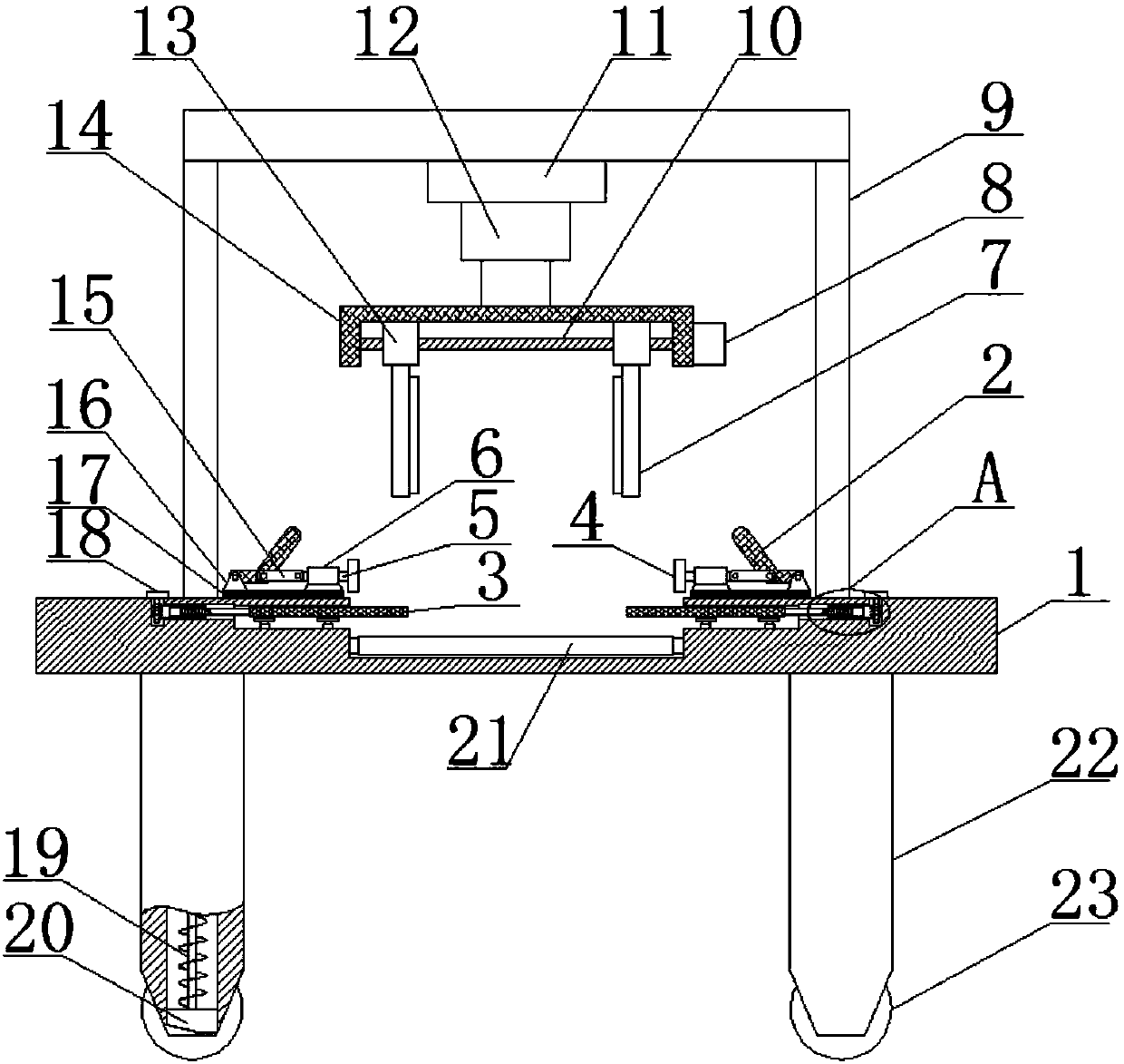
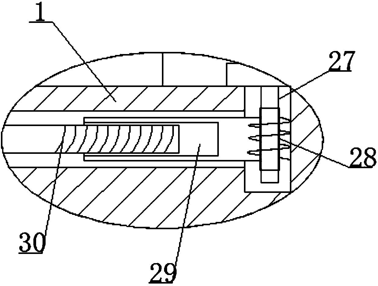
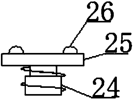
[0026] refer to Figure 1-4 , a device for improving the experimental capability of electric capacitors, comprising a base 1, the upper middle of the base 1 is provided with a conveying trough, and a plurality of conveying rollers 21 are arranged in the conveying trough, and the conveying rollers 21 are connected to the inner wall of the conveying trough by rotating shafts, The inside of base 1 is provided with device cavity, and the upper end of base 1 is provided with worm screw 27, and worm screw 27 runs through the side wall of base 1 and extends in the device cavity, and one end of worm screw 27 is rotatably connected on the inwall of device cavity, and the other...


PUM


Abstract

The invention discloses a device for improving the test ability of a power capacitor. The device comprises a base; a conveying groove is formed in the middle of the upper end of the base; multiple conveying rollers are arranged in the conveying groove and are rotationally connected onto the inner wall of the conveying groove through rotating shafts; a device cavity is formed in the base; worms arearranged at the upper end of the base, penetrate through the side wall of the base and extend into the device cavity; one end of each worm is rotationally connected onto the inner wall of the devicecavity; a rotating wheel is arranged at the other end of each worm; worm gears are arranged in the device cavity; one end of each worm gear is rotationally connected onto the side wall of the device cavity; a cylinder is arranged at the end, far away from the inner wall of the device cavity, of each worm gear; and a strip-shaped groove is formed in the inner wall of the conveying groove. The device is reasonable in structural design and easy to operate, the labor intensity of a worker is effectively reduced, the working efficiency is improved, and meanwhile, the test ability of the power capacitor is improved.

Description

technical field [0001] The invention relates to the technical field of capacitor testing, in particular to a device for improving the experimental capability of power capacitors. Background technique [0002] At present, the power capacitor test device is to perform electrical performance withstand voltage test and dielectric loss test on a single capacitor. The whole process is as follows: [0003] 1 The product is on the track and reaches the test area; [0004] 2 Connect the upper electrode of the capacitor with a cable, and conduct a withstand voltage test and a dielectric loss test on the capacitor through the test system; [0005] 3 The product leaves the test area and arrives at the next process paint line; [0006] The disadvantages of the above-mentioned test device are as follows: [0007] 1 Only a single power capacitor can be tested; [0008] 2 The contact resistance between the upper electrode of the capacitor and the cable clamp is too large, and the temper...

Claims


Application Information

Patent Timeline
IPC IPC(8): B65G47/90B65G13/00G01R31/00
CPCB65G13/00B65G47/90B65G2201/0214G01R31/00
Inventor 林海张和平万美云邢朝东
Owner ANHUI JIANGWEI PRECISION IND
Learn More