Eureka AIR delivers breakthrough ideas for toughest innovation challenges, trusted by R&D personnel around the world.

Cutting machine

A technology for cutting machines and adjusting motors, which is applied in metal processing and other fields, and can solve problems such as unsatisfactory continuous punching operations and affecting production efficiency.

Pending Publication Date: 2018-03-23
广东鸿钢智能装备有限公司
View PDF7 Cites 0 Cited by
  • Summary
  • Abstract
  • Description
  • Claims
  • Application Information

AI Technical Summary

Problems solved by technology

[0002] Cutting machine is a kind of common plate processing equipment. The existing cutting machines mainly include manual operation and mechanical processing. Manual operation needs to manually put materials into the cutting machine, and then operate the cutting machine, which affects production efficiency; and mechanical processing solves the problem. The problem of manual operation of the cutting machine is that it can only punch a single material, which cannot meet the continuous punching operation after the on-line production of plastic materials, sheets, etc. At the same time, the opening distance between the pressing plates needs to be adjusted according to the specifications of the materials and dies. Adjustment is also a problem to be solved

Method used


Image

  • Cutting machine
  • Cutting machine
  • Cutting machine

Examples


Embodiment Construction

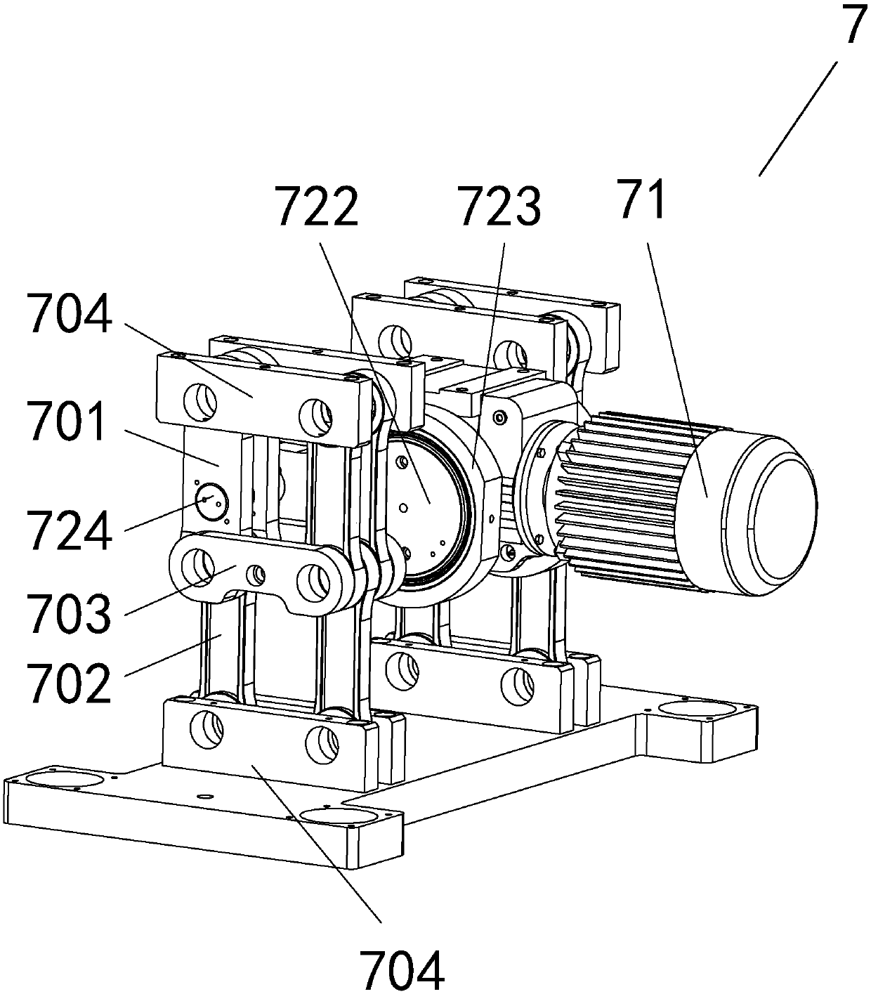
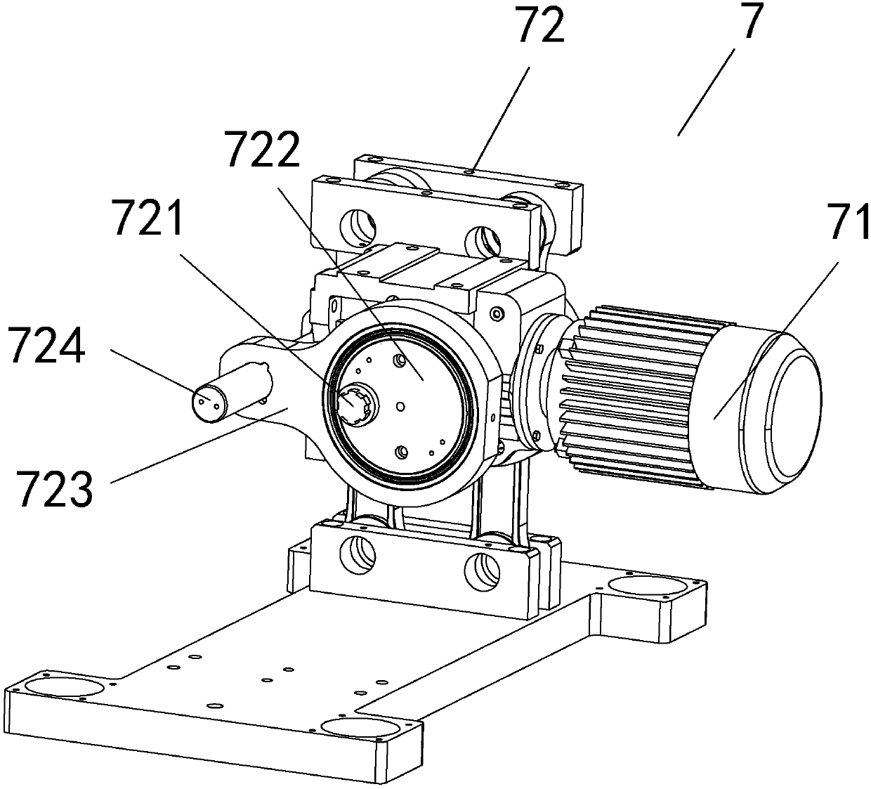
[0022] refer to figure 1 , a cutting machine, comprising a base 1, a lower base plate 2, an upper fixed plate 3, a guide column 4 is installed between the lower base plate 2 and the upper fixed plate 3, the guide column 4 is mounted on the four corners of the lower base plate 2, and the upper fixed plate 3 is installed on the upper end of the guide column 4; and between the lower bottom plate 2 and the upper fixed plate 3, an upper pressing plate 5 and a lower pressing plate 6 that can move vertically on the guiding column 4 are installed in sequence from top to bottom, and the upper pressing plate 5 and the lower pressing plate 6 The knife die is installed on the top, so that the punching operation of the material is completed after the upper press plate 5 and the lower press plate 6 move in opposite directions; in order to drive the upper press plate 5 and the lower press plate 6 to move in opposite directions, The upper fixed plate 3 and the lower base plate 2 are respectiv...


PUM


Abstract

The invention discloses a cutting machine. The cutting machine comprises a base, a lower base plate, an upper fixing plate, and guide vertical columns, wherein an upper pressing plate and a lower pressing plate are mounted between the lower base plate and the upper fixing plate; an opening regulating component connected with the guide vertical columns is arranged at the top end of the upper fixingplate; the base is connected with the lower base plate through a horizontal movement mechanism; the upper pressing plate and the lower pressing plate are closed and opened at a time to complete primary punching operation, the cutting machine moves forwards horizontally through the horizontal movement mechanism to a next work station to carry out the punching operation again, the cutting machine further moves forwards horizontally through the horizontal movement mechanism to a work station, so that the repeated cycle operation is completed, and when the cutting machine moves forwards horizontally for the maximum stroke, the punching operation is completed continuously; meanwhile, the height of the upper fixing plate is reduced through the opening regulating mechanism, the height of the upper pressing plate connected with the upper fixing plate is reduced, the opening distance between the upper pressing plate and the lower pressing plate is changed, the cutting machine can be adapted tomaterials and cutting dies with different dimensions, and the cutting machine has the advantages of strong universality and continuous punching capability.

Description

technical field [0001] The invention relates to the field of material processing equipment, in particular to a cutting machine. Background technique [0002] Cutting machine is a kind of common plate processing equipment. The existing cutting machines mainly include manual operation and mechanical processing. Manual operation needs to manually put materials into the cutting machine, and then operate the cutting machine, which affects production efficiency; and mechanical processing solves the problem. The problem of manual operation of the cutting machine is that it can only punch a single material, which cannot meet the continuous punching operation after the on-line production of plastic materials, sheets, etc. At the same time, the opening distance between the pressing plates needs to be adjusted according to the specifications of the materials and dies. Adjustment is also a problem to be solved. Contents of the invention [0003] In order to overcome the deficiencies ...

Claims


Application Information

Patent Timeline
IPC IPC(8): B26F1/02B26D5/14
CPCB26D5/14B26F1/02
Inventor 孔令强李启明章华陈智伟李德钦侯荣清
Owner 广东鸿钢智能装备有限公司
Why Eureka
Eureka Blog
Learn More