
Compact type compliant orthogonal displacement amplifying mechanism with gain being increased with input force

A technology of displacement amplifying mechanism and input force, applied in the directions of manipulators, manufacturing tools, etc., can solve the problems of reduced mechanism gain, disadvantage, disadvantage of compactness, etc., and achieve the effect of improving accuracy and increasing input force

Inactive Publication Date: 2018-03-23
FOSHAN UNIVERSITY
View PDF0 Cites 0 Cited by
  • Summary
  • Abstract
  • Description
  • Claims
  • Application Information

AI Technical Summary

Problems solved by technology

[0004] Among the existing compliant orthogonal displacement amplification mechanisms, the bridge type amplification mechanism is a typical implementation form, but this mechanism can only achieve orthogonal displacement conversion under the condition of bidirectional symmetrical input force, thus limiting its application range
Although some compliant orthogonal displacement amplification mechanisms can achieve orthogonal displacement amplification under the condition of unidirectional input force, due to geometric nonlinearity, as the input force increases, the gain of the mechanism gradually decreases, so it is not conducive to large-scale work. Realization of space and flexible micro-operations
Although some compliant orthogonal displacement amplification mechanisms can achieve orthogonal displacement amplification under the condition of unidirectional input force, and considering the geometric nonlinearity, the gain of the mechanism is basically constant as the input force increases, but due to the use of Multi-stage mechanism type, therefore not conducive to compactness

Method used


Image

  • Compact type compliant orthogonal displacement amplifying mechanism with gain being increased with input force
  • Compact type compliant orthogonal displacement amplifying mechanism with gain being increased with input force
  • Compact type compliant orthogonal displacement amplifying mechanism with gain being increased with input force

Examples


Embodiment

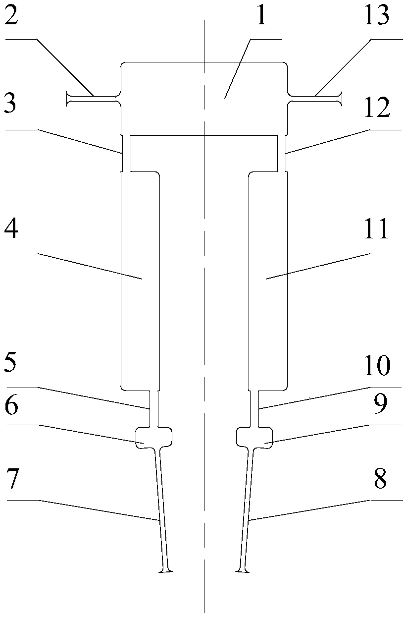
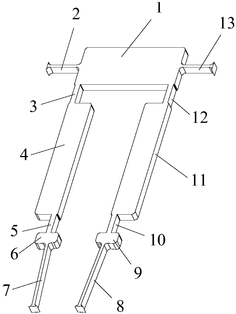
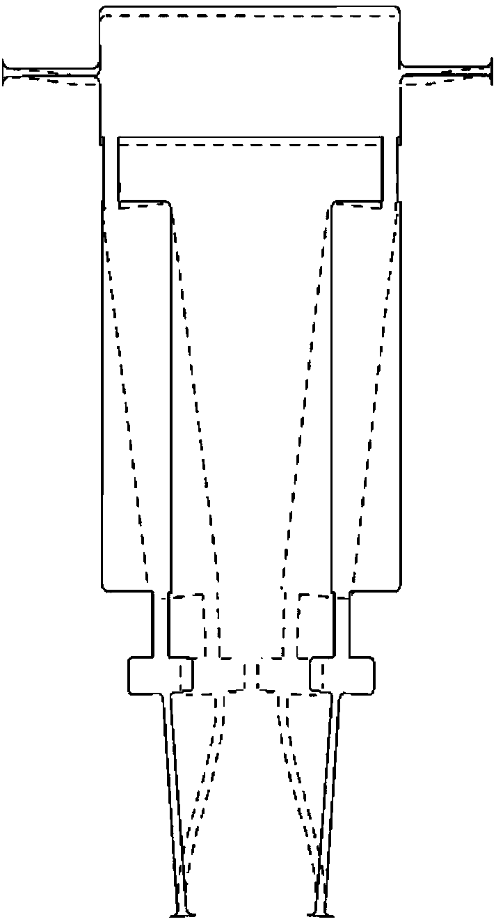
[0039] Such as Figure 1 to Figure 3 As shown, the present invention is a compact compliant orthogonal displacement amplifying mechanism whose gain increases with the input force, which includes a rigid input end 1 for the input force, a left rigid output end 6, a right rigid output end 9, and a left variable section Beam, right variable section beam, left undetermined equal straight beam 7 and right undetermined equal straight beam 8, wherein the left variable section beam, left rigid output end 6 and left undetermined equal straight beam 7 are connected in sequence, and the left variable section beam is far away from the left rigid One end of the output end 6 is connected to the lower end surface of the rigid input end 1, and the right variable-section beam, the right rigid output end 9 and the right undetermined straight beam 8 are connected in sequence, and the end of the right variable-section beam far away from the right rigid output end 9 is connected to the rigid input ...


PUM


Abstract

The invention provides a compact compliant orthogonal displacement amplification mechanism whose gain increases with the input force, including a rigid input end for the input force, a left rigid output end, a right rigid output end, a left variable section beam, and a right variable section beam , the left undetermined equal straight beam and the right undetermined equal straight beam; the left variable cross-section beam, the left rigid output end and the left undetermined equal straight beam are connected sequentially, and the end of the left variable cross section beam far away from the left rigid output end is connected with the lower surface of the rigid input end; The variable cross-section beam, the right rigid output end and the right undetermined straight beam are connected sequentially, and the end of the right variable cross-section beam far away from the right rigid output end is connected to the lower end face of the rigid input end; the left variable cross-section beam, the left rigid output end and the left undetermined equal straight beam It is mirror-symmetrically arranged with the right variable cross-section beam, the right rigid output end and the right undetermined equal straight beam along the central axis of the rigid input end. The mechanism of the invention can realize orthogonal displacement conversion and displacement amplification under the action of unidirectional input force, and has the advantage that the mechanism gain increases with the input force.

Description

technical field [0001] The invention relates to a compliant displacement amplifying mechanism, and more specifically relates to a compact compliant orthogonal displacement amplifying mechanism whose gain increases with input force, which can be applied to fields such as precision engineering and micro-manipulation robots. Background technique [0002] The compliant mechanism refers to a mechanism that uses the elastic deformation of its flexible part to transmit or convert force, motion or energy. Because the compliant mechanism has the advantages of no friction, no gap, no lubrication, no assembly and high motion precision, it is widely used. Used in precision engineering, micro-operation and other fields. [0003] In precision engineering and micro-operation, on the one hand, it is often necessary to expand the limited output stroke of the driver (such as piezoelectric stack driver, electrostatic comb driver) to achieve a large working space and flexible micro-operation; o...

Claims


Application Information

Patent Timeline
IPC IPC(8): B25J19/00
CPCB25J19/00
Inventor 陈为林卢清华
Owner FOSHAN UNIVERSITY
Learn More