Soil beating crusher used for soil remediation

A technology of soil remediation and crushing machine, applied in the field of soil remediation, can solve the problems of poor mobility, single crushing action, high one-time investment, etc., and achieve good crushing effect, simple principle and novel structure

Inactive Publication Date: 2018-03-23
合肥挺泰环保科技有限公司
View PDF0 Cites 1 Cited by
  • Summary
  • Abstract
  • Description
  • Claims
  • Application Information

AI Technical Summary

Problems solved by technology

[0002] With people's increasing awareness of environmental protection, soil remediation is the top priority of the current environmental protection task. During the process of soil remediation, it is unavoidable to break up the larger soil clods, and most of the current smashing work It is done by large machinery, which consumes a lot of electric energy. At the same time, this type of device has a high one-time investment, which hinders the development of small enterprises and restricts the development of the soil remediation industry. For these large The equipment occupies a large area and has poor mobility. It can only be operated with the equipment as the center, and the equipment cannot be easily transported to the polluted site. Shattering effect cannot be guaranteed

Method used


Image

  • Soil beating crusher used for soil remediation
  • Soil beating crusher used for soil remediation
  • Soil beating crusher used for soil remediation

Examples


Embodiment Construction

[0016] The following will clearly and completely describe the technical solutions in the embodiments of the present invention with reference to the accompanying drawings in the embodiments of the present invention. Obviously, the described embodiments are only some, not all, embodiments of the present invention.

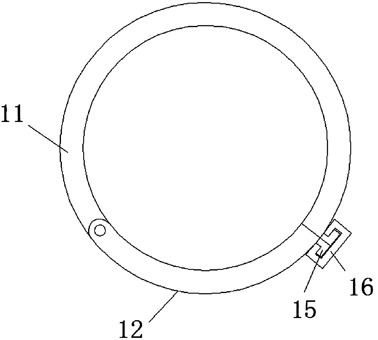
[0017] refer to Figure 1-3 , a soil breaker for soil restoration, comprising a broken soil barrel 11, four vertical legs 1 are arranged on the bottom rectangular ring of the broken soil barrel 11 to support the whole device, and the four vertical legs 1 and the broken soil barrel 11 Fixed connection, the side of the crushing cylinder 11 away from the vertical leg 1 is fixedly connected with the feeding plate 10 communicating with the crushing cylinder 11, which is convenient for the soil block to enter the mechanism, and the side of the crushing cylinder 11 close to the vertical leg 1 is hinged with a discharge The plate 12 is convenient for the crushed soil particl...


PUM


Abstract

The invention discloses a soil breaking machine for soil restoration, which comprises a soil crushing cylinder, four vertical legs are arranged on the bottom side of the rectangular ring of the soil crushing cylinder, and the four vertical legs are fixedly connected with the soil crushing cylinder. The side of the crushing barrel far away from the vertical leg is fixedly connected with a feed plate communicating with the crushing barrel, and the side of the crushing barrel close to the vertical leg is hinged with a discharge plate, and the discharge plate is far away from its hinge. One side is fixedly connected with a bump, and the crushing tube is also fixedly connected with a bump corresponding to the bump on the discharge plate, and two blocks are sleeved on the two bumps, and the center of the crushing tube is inserted. A main shaft is provided, and the outer side of the main shaft located inside the crushing cylinder is fixedly connected with a plurality of crushing claws. The end of the main shaft away from the crushing claws is covered with a moving plate, and the side of the moving plate away from the main shaft is fixedly connected with a motor. The invention has a novel structure. When the main shaft is rotated, the lead screw is used to make the main shaft do a reciprocating linear motion in the soil crushing cylinder, so that the crushing effect is better.

Description

technical field [0001] The invention relates to the field of soil restoration, in particular to a soil breaker for soil restoration. Background technique [0002] With people's increasing awareness of environmental protection, soil remediation is the top priority of the current environmental protection task. During the process of soil remediation, it is unavoidable to break up the larger soil clods, and most of the current smashing work It is done by large machinery, which consumes a lot of electric energy. At the same time, this type of device has a high one-time investment, which hinders the development of small enterprises and restricts the development of the soil remediation industry. For these large The equipment occupies a large area and has poor mobility. It can only be operated with the equipment as the center, and the equipment cannot be easily transported to the polluted site. Shattering effect cannot be guaranteed. Contents of the invention [0003] The purpos...

Claims


Application Information

Patent Timeline
Patent Type & Authority Applications(China)
IPC IPC(8): B02C13/10B02C13/28B02C13/30B02C13/286B09C1/00
CPCB02C13/10B02C13/28B02C13/286B02C13/30B02C2013/28609B09C1/00
Inventor 吴小飞
Owner 合肥挺泰环保科技有限公司
Why Eureka
Try Eureka