
A sensor installation mechanism in a bridge health monitoring system

A bridge health monitoring and installation mechanism technology, which is applied in the direction of measuring devices, measuring instrument components, instruments, etc., can solve problems such as vibration data errors, and achieve the effects of reducing data errors, good close contact, and uniform force

Inactive Publication Date: 2020-05-05
CHENGDU SHANGJIA PHOTOELECTRIC TECH CO LTD
View PDF8 Cites 0 Cited by
  • Summary
  • Abstract
  • Description
  • Claims
  • Application Information

AI Technical Summary

Problems solved by technology

[0009] The present invention solves the problem that in the process of using the vibration sensor in the bridge health monitoring system existing in the prior art, the bridge itself will vibrate due to external effects during the use process, and the vibration will cause the bolts connecting the vibration sensor and the bridge deck to loosen, thereby As a result, there are certain errors in the collected vibration data. A sensor installation base for bridge health monitoring is provided, which can ensure that the vibration sensor is tightly connected to the bridge deck when the connecting bolts are loose, thereby reducing the error of vibration data.

Method used


Image

  • A sensor installation mechanism in a bridge health monitoring system
  • A sensor installation mechanism in a bridge health monitoring system

Examples


Embodiment 1

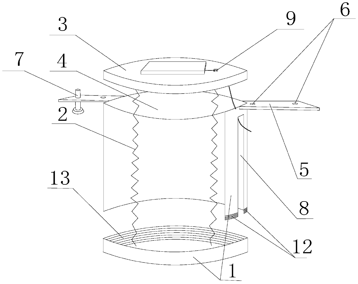
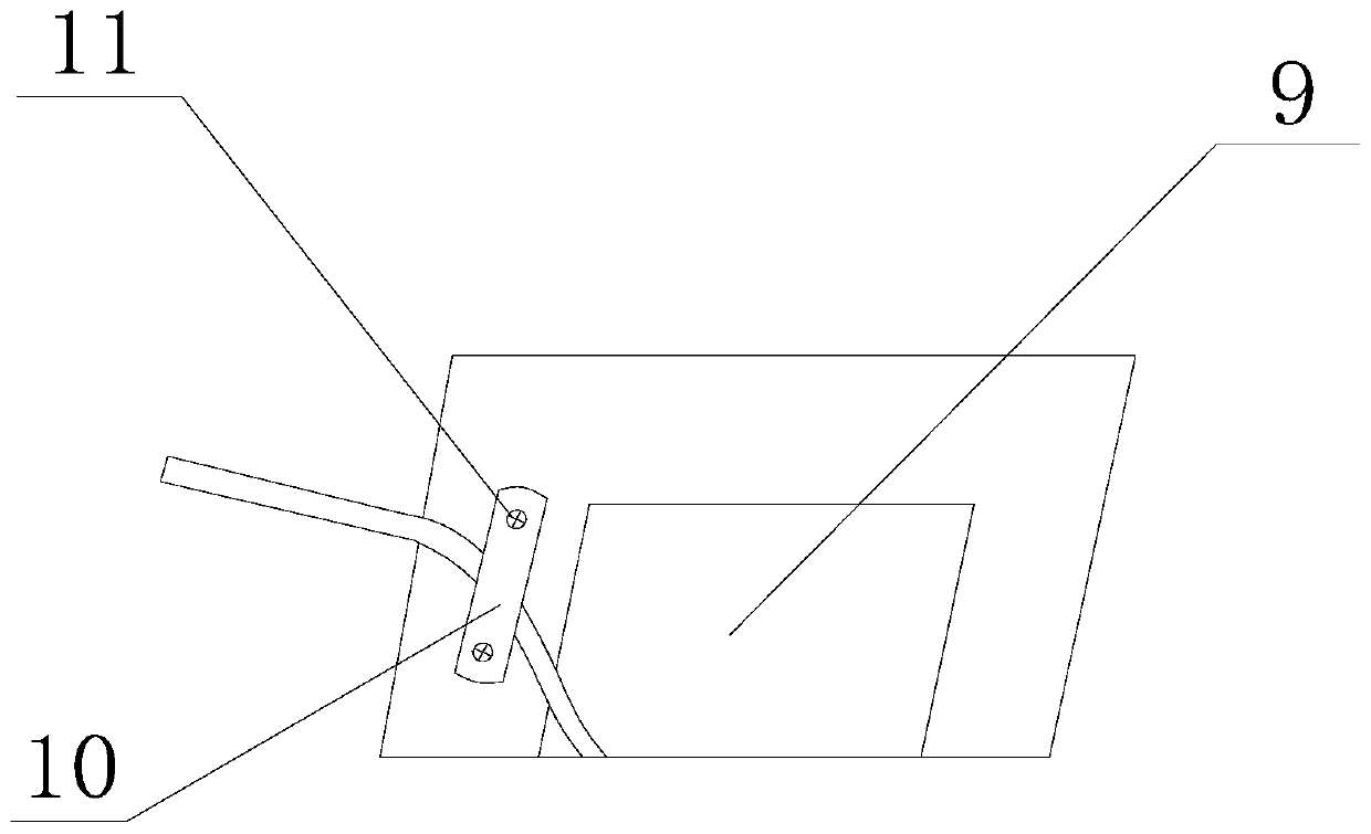
[0026] like Figure 1-2As shown, a sensor installation mechanism in a bridge health monitoring system includes a housing 1, a spring 2, and a support plate 3. An opening 4 is arranged above the housing 1, and a plurality of hanging ears 5 are arranged on the housing 1. The hanging ears 5 Symmetrical with the hanging lug 5 through the central axis of the shell 1, the hanging lug 5 is perpendicular to the side of the shell 1, and at least one threaded hole 6 is provided on the hanging lug 5, and the shell 1 is connected to the bridge deck through a screw 7 matching the threaded hole 6. The shell 1 The side is provided with a wiring port 8, and the lower end opening of the wiring port 8 is in contact with the bottom surface of the shell 1. The shell 1 is a detachable bottom surface. The bottom end of the side of the shell 1 is provided with an external thread 12. 12 with matching internal thread 13 . One end of the support plate 3 close to the wiring opening 8 is provided with a...

Embodiment 2

[0028] On the basis of Embodiment 1, when the vibration sensor itself is damaged, the bottom surface of the entire casing 1 together with the spring 2 and the support plate 3 can be taken out from the inside of the casing 1 by removing the bottom surface of the casing 1, and the connecting cable passes through the wiring port 8 Slide down directly from the side of the shell 1, replace the new vibration sensor, and then make the vibration sensor contact with the bridge deck through the inside of the shell 1, and then compress the spring 2 to connect the bottom surface of the shell 1 with the side of the shell 1. The time for replacing the vibration sensor is shortened, the operation is convenient and fast, the labor cost is saved, and the vibration sensor can monitor the bridge deck to the greatest extent.


PUM


Abstract

The invention discloses a sensor installation mechanism in a bridge health monitoring system, which includes a housing, a spring, and a support plate. An opening is arranged on the upper side of the housing, and a plurality of hanging ears are arranged on the housing. Symmetrical, the mounting lug is perpendicular to the side of the housing, and there is at least one threaded hole on the mounting lug. The housing is connected to the bridge deck through a screw that matches the threaded hole. There is a wiring port on the side of the housing, and the lower opening of the wiring port is in contact with the bottom surface of the housing. , one end of the spring is vertically connected to the inner bottom surface of the casing, the other end of the spring is vertically connected to the support plate, and the support plate matches the opening. The spring acts on the vibration sensor in real time to ensure that the vibration sensor is in close contact with the bridge deck, avoiding the phenomenon of loose contact between the vibration sensor and the bridge deck due to bridge vibration, and reducing the data error collected by the vibration sensor when the screw is loose.

Description

technical field [0001] The invention relates to bridge health monitoring, in particular to a sensor installation mechanism in a bridge health monitoring system. Background technique [0002] As an integral part of the transportation system, bridges have played an important role in the development and evolution of human civilization. With the development of modern technology and the continuous growth of transportation demand, more and more large bridges (such as sea-crossing bridges, long-span bridges, etc.) appear in people's field of vision. It has important strategic significance in terms of transportation, military and social life. [0003] However, during the construction and use of the bridge, due to the erosion of the environment, harmful substances, vehicles, wind, earthquakes, fatigue, human factors, etc., as well as the continuous degradation of the properties of the materials themselves, the structural parts are far from reaching the design life. Different degree...

Claims


Application Information

Patent Timeline
Patent Type & Authority Patents(China)
IPC IPC(8): G01D11/30G01H17/00
CPCG01D11/30G01H17/00
Inventor 卿光弼李自强冉文俊
Owner CHENGDU SHANGJIA PHOTOELECTRIC TECH CO LTD
Learn More