
Active chilled beam and chilled beam air conditioner system

An air-conditioning system, an active technology, applied in air-conditioning systems, heating and ventilation control systems, heating and ventilation safety systems, etc. Thermal comfort requirements, ensuring comfort, and saving energy

Pending Publication Date: 2018-03-20
TSINGHUA UNIV
View PDF8 Cites 7 Cited by
  • Summary
  • Abstract
  • Description
  • Claims
  • Application Information

AI Technical Summary

Problems solved by technology

[0004] However, the above-mentioned active chilled beam air conditioner terminal has the following defects. It is mainly used in the scene of mixed air supply, the direction of air supply cannot be changed, the characteristics of air supply are single, the form of air supply at the end cannot be adjusted, and the energy consumption is high.

Method used


Image

  • Active chilled beam and chilled beam air conditioner system
  • Active chilled beam and chilled beam air conditioner system
  • Active chilled beam and chilled beam air conditioner system

Examples


Embodiment 1

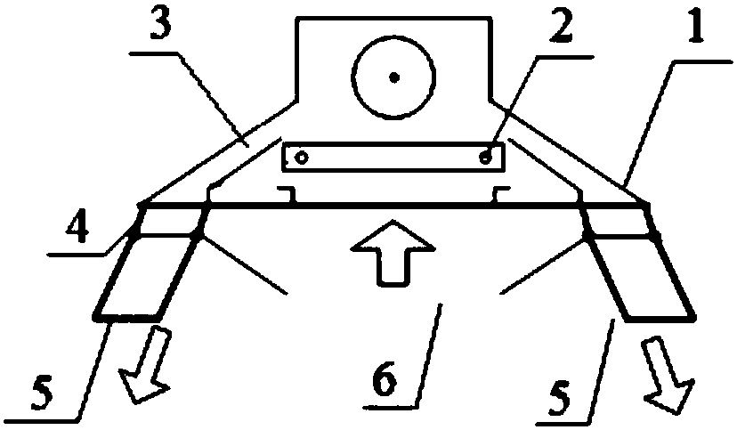
[0036] Such as figure 2 As shown, an active chilled beam provided in this embodiment includes a housing 1, the bottom of the housing 1 is provided with an air inlet 6, both sides of the housing 1 are provided with an air outlet 4, and the housing 1 is provided with There are heat exchange coils 2 and an air outlet duct 3 communicating with the air outlet 4, and a rotatable wind guide vane 5 is provided at the air outlet 4.

[0037] In this embodiment, the air outlet 4 is provided with a fixed end of the wind guide vane, and the wind guide vane 5 is rotatably connected to the fixed end of the wind guide vane through a rotating shaft.

[0038] Wherein, the angle between the wind guide vane 5 and the vertical direction is the rotation angle. In this embodiment, the rotation angle is 0-90°. And the wind guide vane 5 can rotate inwardly and outwardly.

[0039] Further, a fresh air inlet is provided on the housing, and the fresh air inlet communicates with the ventilation pipe o...

Embodiment 2

[0051] Such as Figure 7 As shown, the present embodiment provides a chilled beam air conditioning system, including the natural energy harvesting device 7 and the above-mentioned active chilled beam.

[0052] The water outlet pipe of the natural energy collection device 7 is connected to the water inlet of the heat exchange coil 2 , and the water inlet pipe of the natural energy collection device 7 is connected to the water outlet of the heat exchange coil 2 . A natural energy harvesting device is used to provide cold water to the heat exchange coil.

[0053] Specifically, in this embodiment, the connection pipeline between the natural energy collection device 7 and the water inlet of the heat exchange coil 2 is provided with a first valve 12 and a first water pump 20; A second valve 13 and a second water pump 21 are provided on the connecting pipeline of the water outlet of the pipe 2 .

[0054] Further, an indoor temperature sensor 11 is also included, and the indoor temp...


PUM

PropertyMeasurementUnit
Rotation angleaaaaaaaaaa

Abstract

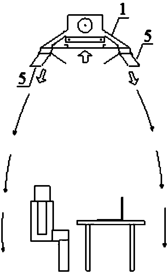
The invention provides an active chilled beam. The active chilled beam comprises a shell body, an air inlet is formed in the bottom of the shell body, and air outlets are formed in the two sides of the shell body; the shell body is internally provided with air outlet channels and heat exchanging coils, wherein the air outlet channels and the heat exchanging coils communicate with the air outlets;and rotatable air guiding wing plates are arranged at the air outlets. On the one hand, the cooling load of all indoor areas is not required to be borne, and the active chilled beam only acts on the indoor specific guaranteed area, so that energy consumption is saved; and on the other hand, the size and the position of the indoor specific guaranteed area can be adjusted by changing the angles of the air guiding wing plates so that the indoor specific guaranteed area can be changed along with indoor personnel activities, and comfortableness is ensured. The invention further provides a chilled beam air conditioner system. The chilled beam air conditioner system comprises a natural energy collecting device and the active chilled beam; and water outlet pipes of the natural energy collecting device are connected with water inlets of the heat exchanging coils, and the natural energy collecting device is used for providing cold water to the heat exchanging coils. Natural energy resources canbe fully utilized to save energy, and the requirement of indoor thermal comfortableness is met.

Description

technical field [0001] The invention relates to the technical field of air conditioning equipment, in particular to an active chilled beam and a chilled beam air conditioning system. Background technique [0002] At present, building energy consumption occupies a high proportion in the total energy consumption of society, and HVAC energy consumption is the main part of building energy consumption. Therefore, it is necessary to reduce building energy consumption and achieve energy saving and emission reduction by optimizing the system and terminal form. The main body of the conventional active chilled beam is a cooling coil, through which the air is exchanged for heat. It is supported by shells on the left and right, similar to the beam installed on the top. After fresh air cooling and dehumidification treatment, it is sent to the static pressure box through the fan. Due to the entrainment effect of the fresh air, the indoor air is sucked in and cooled by the cooling coil, ...

Claims


Application Information

Patent Timeline
IPC IPC(8): F24F1/00F24F13/14F24F5/00F24F11/89F24F140/20F24F110/10
CPCF24F1/0007F24F5/0046F24F13/1413
Inventor 李先庭梁超杨子旭石文星王宝龙
Owner TSINGHUA UNIV
Learn More