
Straw bundling device

A strapping device and straw technology, which is applied in application, packaging, agricultural machinery and tools, etc., can solve the problems of high manufacturing cost and complex structure of straw strapping device, and achieve the effect of simple structure

Pending Publication Date: 2018-03-20
建始惠万农生物科技有限公司
View PDF0 Cites 6 Cited by
  • Summary
  • Abstract
  • Description
  • Claims
  • Application Information

AI Technical Summary

Problems solved by technology

[0003] The purpose of the present invention is to solve the problem of complex structure and high manufacturing cost of the straw binding device in the prior art, and propose a straw binding device

Method used

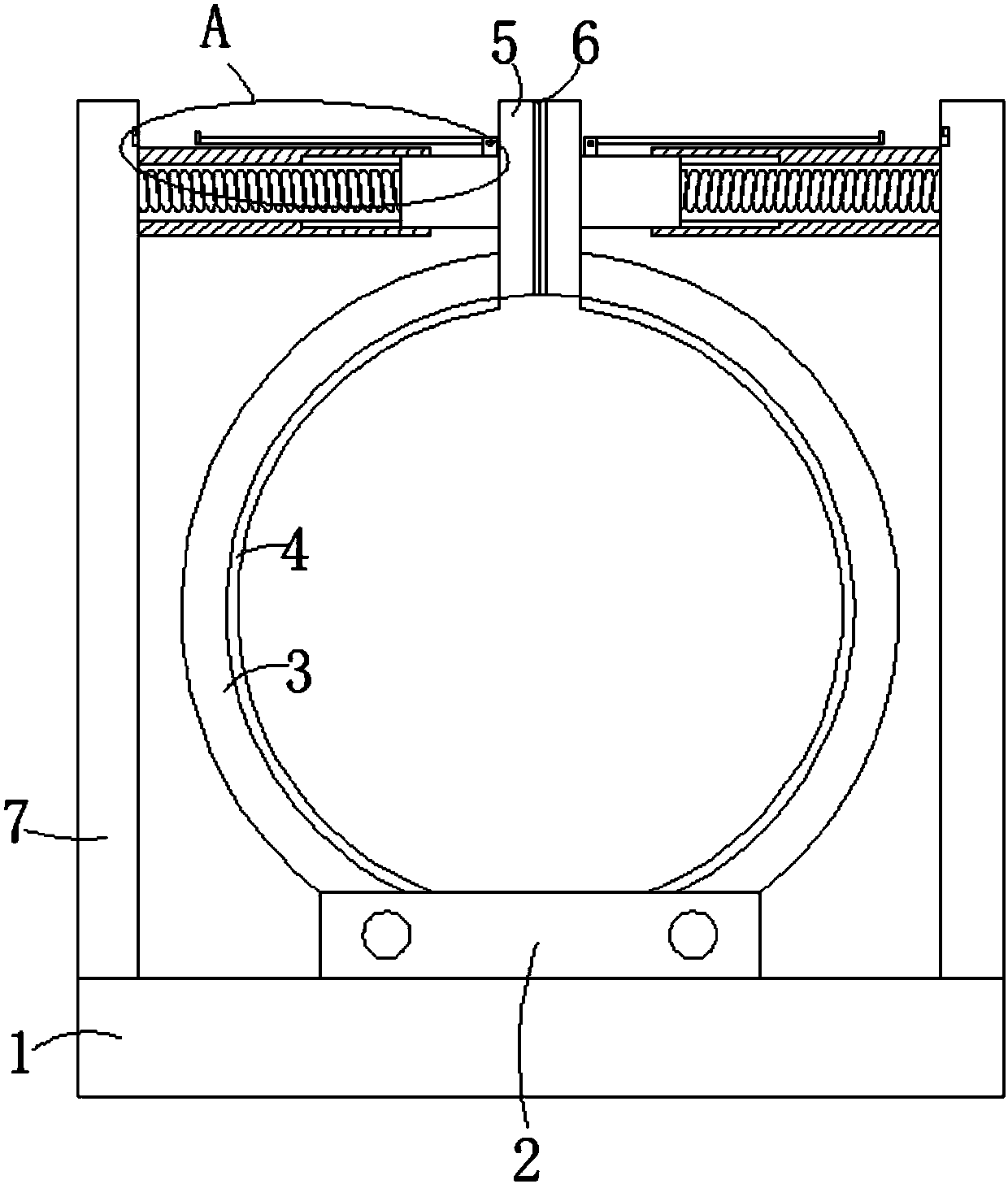
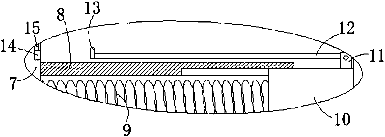

Image

  • Straw bundling device
  • Straw bundling device

Examples


Embodiment Construction

[0015] The following will clearly and completely describe the technical solutions in the embodiments of the present invention with reference to the accompanying drawings in the embodiments of the present invention. Obviously, the described embodiments are only some, not all, embodiments of the present invention.

[0016] In describing the present invention, it should be understood that the terms "upper", "lower", "front", "rear", "left", "right", "top", "bottom", "inner", " The orientation or positional relationship indicated by "outside", etc. is based on the orientation or positional relationship shown in the drawings, and is only for the convenience of describing the present invention and simplifying the description, rather than indicating or implying that the referred device or element must have a specific orientation, so as to Specific orientation configurations and operations, therefore, are not to be construed as limitations on the invention.

[0017] refer to Figure ...


PUM


Abstract

The invention discloses a straw bundling device. The device includes a bottom plate, a fixing plate is fixedly connected with the upper surface of the bottom plate, two arc-shaped clamping plates arerotatingly connected with the fixing plate, each of the inner side walls of the clamping plates is provided with an accommodating tank for accommodating a bundling rope, the upper end of each clampingplate is fixedly connected with a vertical plate, each of two opposite side walls of the vertical plates is provided with a threading groove, one side of each vertical plate is provided with a baffle, the lower ends of the baffles are fixedly connected with the upper surface of the bottom plate, one side wall of each baffle is fixedly connected with a cylinder, a spring is arranged in each cylinder, one end of each spring is fixedly connected with the side wall of one baffle, and the other end of each spring is fixedly connected with a blocking block, each blocking block is slidably connectedwith the inner side of one cylinder, and one end surface, far away from one spring, of each blocking block is in contact with the side wall of one vertical plate. The straw bundling device provided by the invention realizes the purpose of effectively bundling straws, and the structure of the device is simple, so that the straw bundling device is worthy to be promoted.

Description

technical field [0001] The invention relates to a binding device, in particular to a straw binding device. Background technique [0002] Straw is called stalk in ancient times, and wheat straw is called wheat straw. However, the structure of the existing straw binding device is complicated and the manufacturing cost is high. Straw is bundled in a traditional way, so we propose a straw bundling device to solve the above problems. Contents of the invention [0003] The purpose of the present invention is to solve the problems of complex structure and high manufacturing cost of the straw binding device in the prior art, and propose a straw binding device. [0004] In order to achieve the above object, the present invention adopts the following technical solutions: [0005] A straw binding device, comprising a bottom plate, the upper surface of the bottom plate is fixedly connected with a fixed plate, and two arc-shaped clamping plates are rotatably connected to the fixed pl...

Claims


Application Information

Patent Timeline
Patent Type & Authority Applications(China)
IPC IPC(8): A01F15/07A01F15/08A01F15/14
CPCA01F15/07A01F15/08A01F15/141
Inventor 张桂清
Owner 建始惠万农生物科技有限公司
Learn More