Drag calculation method for fluid equipment on the basis of CFD (Computational Fluid Dynamics)

A fluid equipment and resistance calculation technology, applied in the direction of calculation, computer-aided design, design optimization/simulation, etc., can solve problems such as the difficulty of resistance calculation of complex thermal fluid equipment, and reduce the consumption of artificial and computer resources, the number of grids Reduced, computationally simple effects

Active Publication Date: 2018-03-16
国核示范电站有限责任公司
View PDF6 Cites 4 Cited by
  • Summary
  • Abstract
  • Description
  • Claims
  • Application Information

AI Technical Summary

Problems solved by technology

[0006] The object of the present invention is also to provide a resistance calculation method of fluid equipment based on CFD that can solve the difficult problem of resistance calculation of complex thermal fluid equipment

Method used


Image

  • Drag calculation method for fluid equipment on the basis of CFD (Computational Fluid Dynamics)
  • Drag calculation method for fluid equipment on the basis of CFD (Computational Fluid Dynamics)
  • Drag calculation method for fluid equipment on the basis of CFD (Computational Fluid Dynamics)

Examples


Embodiment Construction

[0032] Exemplary embodiments of the present invention will be described in detail below with reference to the accompanying drawings, wherein the same or similar reference numerals represent the same or similar elements. In addition, in the following detailed description, for purposes of explanation, numerous specific details are set forth in order to provide a comprehensive understanding of the embodiments of the present disclosure. It may be evident, however, that one or more embodiments may be practiced without these specific details. In other instances, well-known structures and devices are shown in diagrammatic form to simplify the drawings.

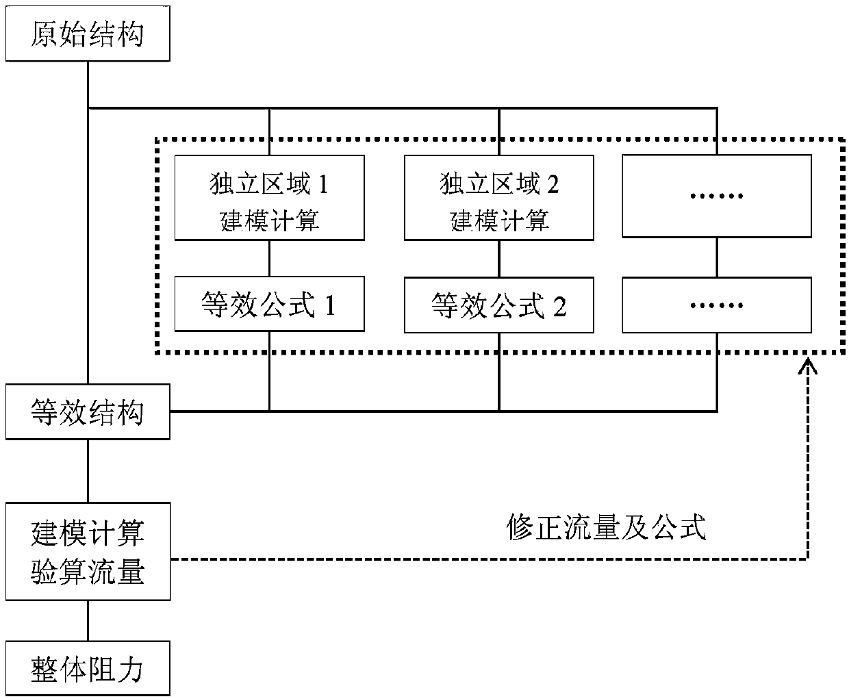
[0033] According to the general inventive concept of the present invention, a method for calculating resistance of fluid equipment based on CFD is proposed, and the resistance value of fluid equipment is calculated by CFD software based on a simplified geometric model of fluid equipment.

[0034] figure 1 It is a schematic diagram ...


PUM


Abstract

The invention provides a drag calculation method for fluid equipment on the basis of CFD (Computational Fluid Dynamics). The method comprises the following steps that: S1: dividing the fluid equipmentinto a plurality of areas of which the flowing are relatively independent; S2: independently dividing a grid for each area; S3: on the basis of the grid of each area, through the CFD software, carrying out CFD analysis to obtain one group of flow-drag data; S4: utilizing quadratic fitting to obtain the curves of the traffic and the drag of each area; S5: simplifying the plurality of areas of which the flowing are relatively independent into a plurality of models with an constant circulation sectional area; S6: dividing the grid for a simplified geometric model, in the CFD software, adding a drag source item to each model with the constant circulation sectional area on the basis of a fitting coefficient obtained by the quadratic fitting; and S7: on the basis of the grid of the simplified geometric model, through the CFD software, carrying out CFD analysis to obtain the preliminary drag value of the fluid equipment. By use of the drag calculation method, the consumption of manual resources and computer resources can be lowered, and calculation accuracy can be improved.

Description

technical field [0001] The invention relates to the field of computer-aided engineering (CAE), in particular to a method for calculating resistance of fluid equipment based on CFD, and more particularly to a method for calculating resistance of complex thermal fluid equipment based on CFD. Background technique [0002] Thermal fluid systems are mostly composed of pipes, valves and main equipment. The power of the working fluid flow in the system usually comes from a pump or compressor, and it matches the flow resistance generated by other components. In the design stage, for the selection of power equipment, the resistance of the system must be estimated. [0003] For pipes, valves and other components, due to their relatively simple structure and certain standardization and serialization characteristics, empirical formulas are used to calculate their resistance, which can meet the accuracy requirements. However, for the main equipment, block equivalent is usually performe...

Claims


Application Information

Patent Timeline
Patent Type & Authority Applications(China)
IPC IPC(8): G06F17/50
CPCG06F30/20G06F2119/08
Inventor 李京浩闫大强陈纲丁炜堃陈义学
Owner 国核示范电站有限责任公司
Why Eureka
Try Eureka