Marine cable wiring mechanism

A technology for marine cables and electric boxes, which is applied in the direction of connection/termination cable equipment, circuits, connections, etc. It can solve the problems of unreasonable structural design and inconvenient use, and achieve the effect of convenient use and simple structural design

Inactive Publication Date: 2018-03-09
马卫华
View PDF0 Cites 0 Cited by
  • Summary
  • Abstract
  • Description
  • Claims
  • Application Information

AI Technical Summary

Problems solved by technology

[0002] The ship is an important means of water transportation. When the cable is assembled on it, the cable needs to be connected. The existing cable connection mechanism for the ship has an unreasonable structural design, inconvenient use, and potential safety hazards.

Method used


Image

  • Marine cable wiring mechanism

Examples


Embodiment Construction

[0009] The present invention will be further explained below in conjunction with the drawings and embodiments.

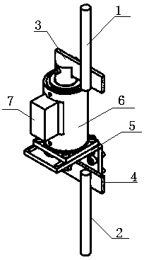
[0010] Such as figure 1 As shown, a marine cable wiring mechanism includes an upper rod 1, a lower rod 2, an upper connecting plate 3, a lower connecting plate 4, a support base 5, an electric box 6 and a photoelectric controller 7. The lower end 2 is provided with The lower connecting plate 4, the lower connecting plate 4 is provided with the supporting base 5, the supporting base 5 is provided with the electric box 6, and one side of the electric box 6 is provided with the photoelectric controller 7. The electric box 6 is provided with the upper rod 1 and the upper connecting plate 3.

[0011] The upper rod 1 and the upper connecting plate 3 are connected.

[0012] The above content is an example and description of the present invention, but it does not mean that the advantages that the present invention can obtain are limited by this. Any simple structural change that...


PUM


Abstract

The invention discloses a marine cable connection mechanism, which comprises an upper pull rod (1), a lower pull rod (2), an upper connecting plate (3), a lower connecting plate (4), a supporting seat (5), an electric box (6) and The photoelectric controller (7), the upper end of the pull-down rod (2) is provided with the lower connection plate (4), the lower connection plate (4) is provided with the support seat (5), and the support seat ( 5) The electric box (6) is provided on the top, the photoelectric controller (7) is provided on one side of the electric box (6), and the upper pull rod (1) is provided on the electric box (6) and upper connection plate (3). The invention has simple structure design, is suitable for ship cable connection, has simple structure design, is convenient to use, and is safe and reliable.

Description

Technical field [0001] The invention relates to the field of ship assembly, in particular to a ship cable wiring mechanism. Background technique [0002] Ships are important water vehicles, and cables need to be wired when cables are assembled on them. The existing ship cable wiring mechanism has unreasonable structural design, inconvenient use, and potential safety hazards. Summary of the invention [0003] The purpose of the present invention is to overcome the problems of the prior art and provide a marine cable wiring mechanism. [0004] A marine cable wiring mechanism of the present invention includes an upper tie rod, a lower tie rod, an upper connecting plate, a lower tie plate, a support base, an electric box, and a photoelectric controller. The upper end of the lower tie rod is provided with the lower connecting plate. The supporting seat is provided on the lower connecting plate, the electric box is arranged on the supporting seat, the photoelectric controller is arranged...

Claims


Application Information

Patent Timeline
IPC IPC(8): H02G1/14H01R43/00
CPCH02G1/14H01R43/00
Inventor 马卫华
Owner 马卫华
Why Eureka
Try Eureka