Holder and control method thereof

A technology of pan/tilt and controller, applied in the direction of using feedback control, etc., can solve problems such as insufficient precision of preset points, limited operation of pan/tilt, etc.

Inactive Publication Date: 2018-03-09
ZHEJIANG DAHUA TECH CO LTD
View PDF7 Cites 2 Cited by
  • Summary
  • Abstract
  • Description
  • Claims
  • Application Information

AI Technical Summary

Problems solved by technology

[0005] Embodiments of the present invention provide a pan / tilt and its control method, which are used to solve the problems of limited pan / tilt operation and insufficient precision of preset points in the prior art

Method used


Image

  • Holder and control method thereof
  • Holder and control method thereof
  • Holder and control method thereof

Examples


Embodiment Construction

[0056] Aiming at the problems of limited operation of the pan / tilt and insufficient precision of preset points in the prior art, an embodiment of the present invention provides a pan / tilt and a control method thereof.

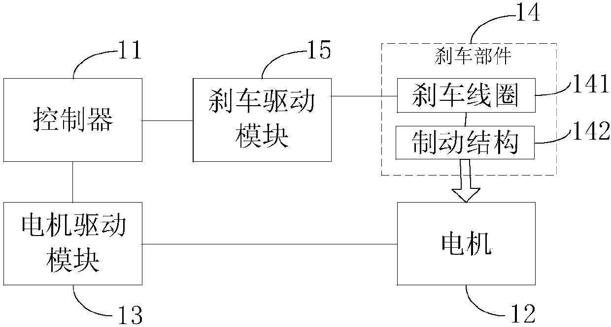
[0057] Such as figure 1 As shown, the pan / tilt provided by the embodiment of the present invention includes: a controller 11, a motor 12, a motor drive module 13, a brake component 14 and a brake drive module 15;

[0058] The controller 11 is respectively connected with the motor drive module 13 and the brake drive module 15; the motor drive module 13 is electrically connected with the motor 12; the brake drive module 15 is connected with the brake component 14;

[0059] The brake component 14 includes: a brake coil 141 and a brake structure 142; the brake coil 141 is electrically connected to the brake structure 142; the brake drive module 15 is connected to the brake coil 141;

[0060] The controller 11 is used to control the brake drive module 15 to make the brake co...


PUM


Abstract

The invention discloses a holder and a control method thereof. The holder comprises: a controller, a motor, a motor drive module, a brake drive module, a brake coil and a brake structure; the controller is connected with the motor drive module and the brake drive module respectively; the controller is used for controlling the brake coil and the motor to be in a power-off state when the holder remains stationary for more than preset time, so that the brake structure brakes the motor; when the holder is unlocked, the controller controls the motor and the brake coil to be in a power-on state, sothat the brake structure is separated from the motor and the holder is unlocked. Therefore, after the controller applies a corresponding electrical signal to the brake coil to unlock the holder, the holder can be controlled accurately. In addition, the holder does not adopt a worm gear structure or a reduction motor, so high-speed rotation of the holder is not affected, and the problems of limit to the operation of the holder and low precision of a preset point are avoided.

Description

Technical field [0001] The invention relates to the field of safety control, in particular to a pan-tilt and its control method. Background technique [0002] The self-locking pan / tilt camera, as the name suggests, refers to when the pan / tilt is stationary, the pan / tilt is locked by a mechanical structure, without the need to apply current to the motor through the motor drive to maintain the pan / tilt state, thereby reducing power consumption. At present, the self-locking pan / tilt mainly realizes the self-locking function through two forms of worm gear and geared motor. [0003] The self-locking pan / tilt based on the worm gear uses the principle that when the lead angle of the worm is smaller than the equivalent friction angle between the worm gear teeth, the mechanism is self-locking, that is, the worm can only be driven by the worm and the worm cannot be driven by the worm. The stage is reversed and self-locking. However, the self-locking pan / tilt based on the worm gear has low ...

Claims


Application Information

Patent Timeline
Patent Type & Authority Applications(China)
IPC IPC(8): G05D3/12
CPCG05D3/12
Inventor 甄建聚
Owner ZHEJIANG DAHUA TECH CO LTD
Why Eureka
Try Eureka