Heat exchanger core for heat exchange between more than three fluids

A technology of heat exchangers and heat exchange fluids, which is applied in the direction of heat exchange equipment, heat exchanger types, indirect heat exchangers, etc., and can solve problems such as inability to realize heat exchange of various fluids

Pending Publication Date: 2018-03-09
AEROSPACE HIWING HARBIN TITANIUM IND
View PDF7 Cites 6 Cited by
  • Summary
  • Abstract
  • Description
  • Claims
  • Application Information

AI Technical Summary

Problems solved by technology

[0002] At present, micro-channel heat exchangers have been widely used in ships, automobiles, air-conditioning and other industries. Due to their small size and light weight, micro-channel heat exchangers have become an important new direction for the research and development of heat exchangers. At present, Multiple fluid heat exchange cannot be achieved with a simple heat exchanger core structure

Method used


Image

  • Heat exchanger core for heat exchange between more than three fluids
  • Heat exchanger core for heat exchange between more than three fluids
  • Heat exchanger core for heat exchange between more than three fluids

Examples


Embodiment 1

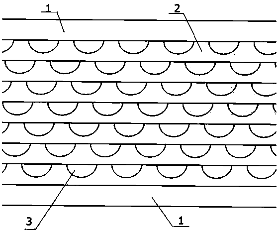
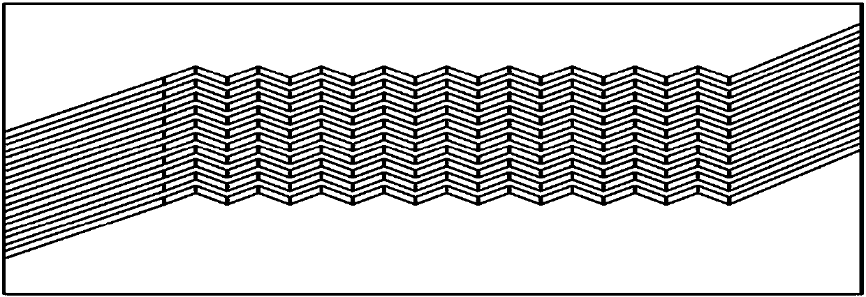
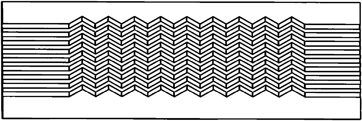
[0034] A heat exchanger core for heat exchange of three fluids: including flow channels and fluid inlets and outlets such as image 3 The heat exchange plate group 1 composed of the shown heat exchange plates, the heat exchange plate group 1 includes more than one such as image 3 The heat exchange plates shown also include flow channels and fluid inlets and outlets such as Figure 4 The heat exchange plate group 2 composed of the shown heat exchange plates, the heat exchange plate group 2 includes more than one such as Figure 4 The heat exchange plates shown also include flow channels and fluid inlets and outlets such as Figure 5 The heat exchange plate group 3 composed of the shown heat exchange plates, the heat exchange plate group 3 includes more than one such as Figure 5 The heat exchange plates shown; the heat exchange channels of all the heat exchange plates are located on one surface of the base body.

[0035] The core of the heat exchanger in this embodiment is ...

Embodiment 2

[0037] The difference from Embodiment 1 lies in that the heat exchange channels of the heat exchange plates are located on one or both sides of the substrate. One side of the heat exchange channels between adjacent heat exchange plates is not adjacent or adjacent, and a partition is provided between two adjacent heat exchange plates on one side of the heat exchange channel, and the partition is not etched The matrix of the heat exchange flow channel, one of the schematic diagrams of the core structure of the heat exchanger is shown in Figure 14 .

Embodiment 3

[0039] The difference with embodiment 1 is: the flow channel and the fluid inlet and outlet are image 3 The heat exchange plates shown are replaced with runners and fluid inlets and outlets as figure 2 The heat exchanger plate shown.


PUM


Abstract

The invention relates to a heat exchanger core for heat exchange between more than three fluids. The heat exchanger core is formed by alternately overlaying a first heat exchange plate group, a secondheat exchange plate group, ..., and an nth heat exchange plate group, wherein each heat exchange plate group bears a first heat exchange fluid, ..., and the nth heat exchange plate group bears an nthheat exchange fluid; each heat exchange plate is composed of a substrate and a heat exchange flow channel machined on the substrate through chemical etching, and the two ends of the heat exchange flow channel are located on the side edge of the substrate and are provided with an inlet and an outlet for the heat exchange fluids respectively. Each heat exchange plate group includes more than more identical heat exchange plate. Projections of fluid inlets and outlets of different heat exchange plate groups in the direction perpendicular to the heat exchange plates are staggered and do not overlap with each other, wherein n is a positive integer no less than 3. According to the heat exchanger core, by reasonable arrangement of the flow channels of the heat exchange plates and the inlets and the outlets, simultaneous heat exchange between multiple fluids is achieved, and the heat exchange plates and the flow channel structures can be designed into any shape and any size, to meet heat exchange requirements.

Description

technical field [0001] The invention belongs to the technical field of heat exchange design, and in particular relates to a heat exchanger core used for heat exchange of more than three fluids. Background technique [0002] At present, micro-channel heat exchangers have been widely used in ships, automobiles, air-conditioning and other industries. Due to their small size and light weight, micro-channel heat exchangers have become an important new direction for the research and development of heat exchangers. At present, Multiple fluid heat exchange cannot be achieved with a simple heat exchanger core structure. Contents of the invention [0003] In order to solve the above problems, the present invention provides a heat exchanger core for heat exchange of more than three fluids, the technical solution is: [0004] The heat exchanger core used for heat exchange of more than three kinds of fluids is composed of the first heat exchange plate group, the second heat exchange p...

Claims


Application Information

Patent Timeline
Patent Type & Authority Applications(China)
IPC IPC(8): F28D9/00F28F3/08
CPCF28D9/0081F28F3/08
Inventor 韩芳明李雪梅王文博肖波刘俊秀崔庆龙刘莹
Owner AEROSPACE HIWING HARBIN TITANIUM IND
Why Eureka
Try Eureka