
Method for the control of the slip of a clutch device of a gearbox

A technology of clutch device and control device, which is applied in the direction of clutch, transmission control, components with teeth, etc., can solve the problems of increased fuel consumption, increased emissions, etc., and achieve the effect of reduced fuel consumption

Active Publication Date: 2018-03-09
DR ING H C F PORSCHE AG
View PDF4 Cites 0 Cited by
  • Summary
  • Abstract
  • Description
  • Claims
  • Application Information

AI Technical Summary

Problems solved by technology

However, this necessarily leads to increased lifetime fuel consumption of the vehicle and to emissions from the vehicle such as CO 2 )Increase

Method used


Image

  • Method for the control of the slip of a clutch device of a gearbox
  • Method for the control of the slip of a clutch device of a gearbox
  • Method for the control of the slip of a clutch device of a gearbox

Examples


Embodiment Construction

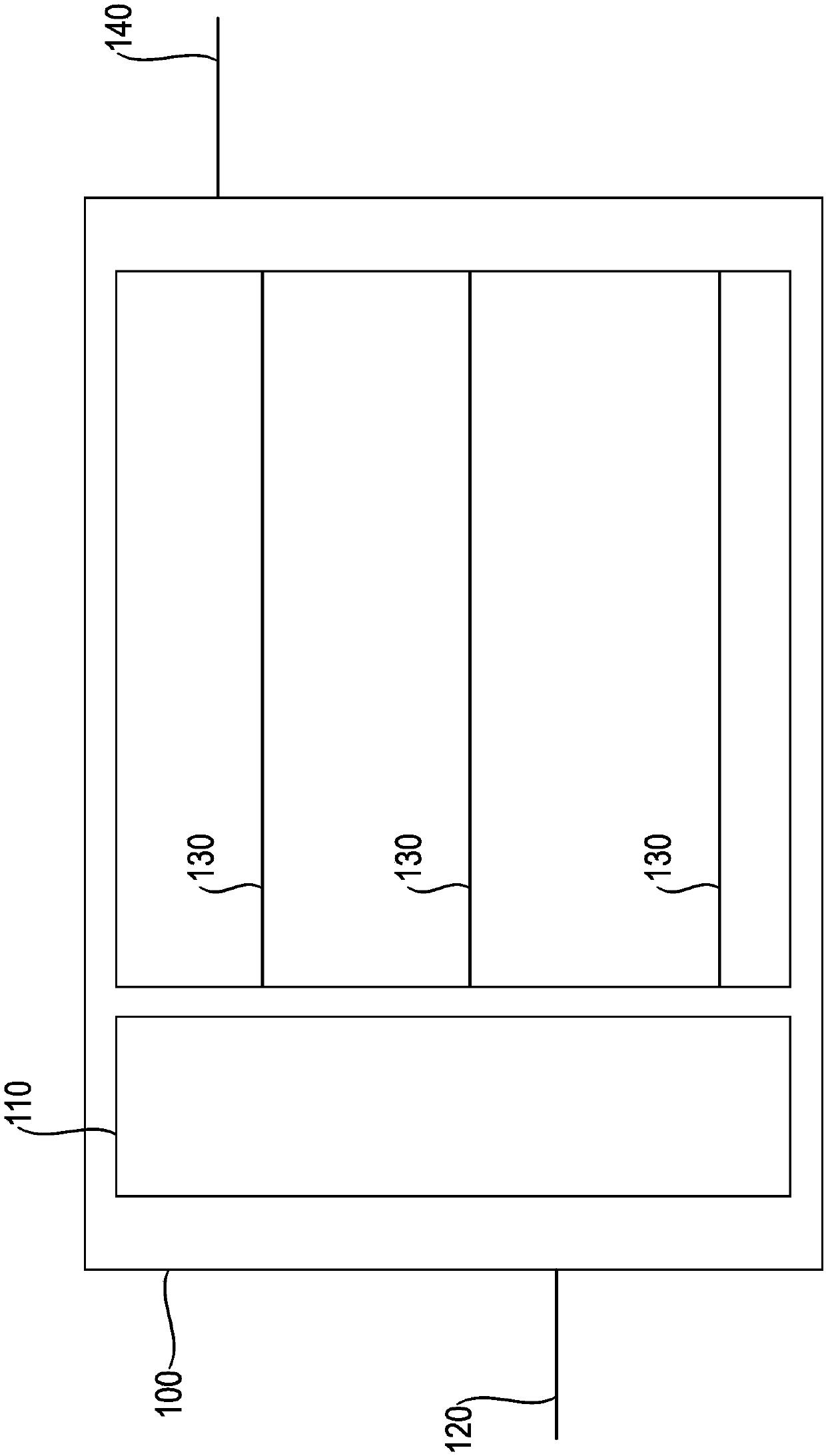
[0033] figure 1 It is schematically shown how the clutch device 110 makes it possible to couple the input shaft 120 with the output shaft 140 in the transmission 100 . In order to be able to ensure different transmission ratios, in this case three transmission shafts 130 are arranged in the transmission 100 so that three different transmission ratios can be selected via three different gears.

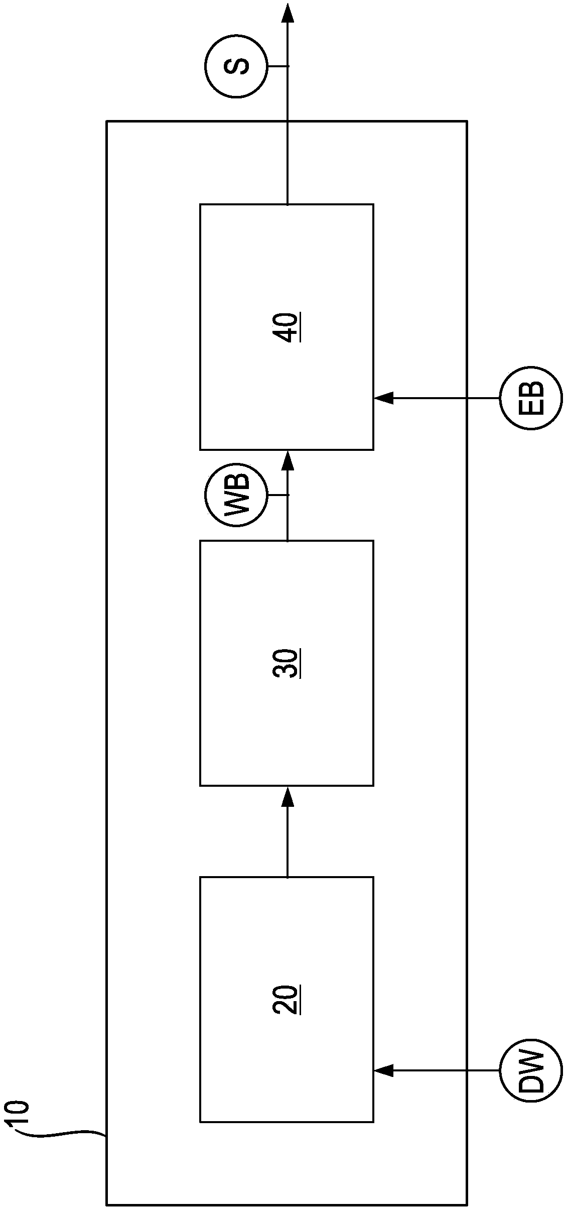
[0034] as in figure 2 schematically shown in, according to figure 1 The transmission 100 is equipped with a control device 10 . By means of the sensor unit 20 , a rotational speed value DW at the transmission shaft 130 can be determined. Based on this rotational speed value and in addition to the information of active transmission shaft 130 , determination unit 30 can then determine angular acceleration WB at determined transmission shaft 130 on the basis of this measured rotational speed value DW. This angular acceleration WB is passed on to the control unit 40, which then determi...


PUM


Abstract

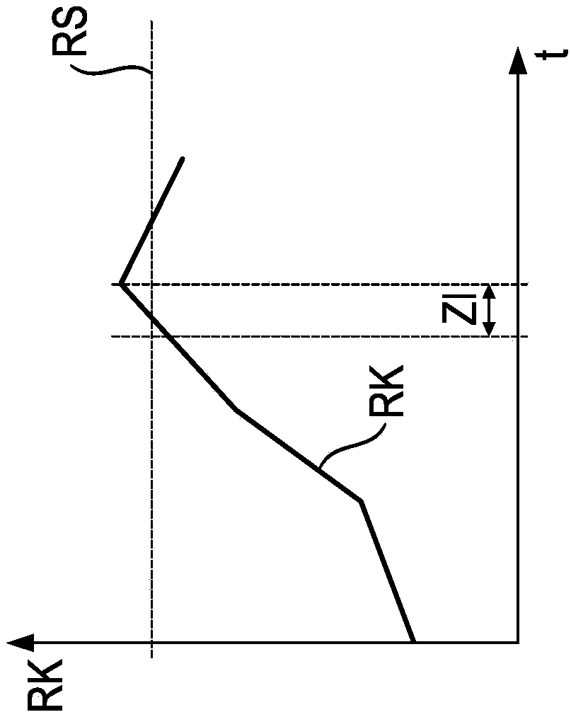
A method for controlling a slip of a clutch device (110) of a gearbox (100) of a vehicle includes measuring at least one rotational speed value (DW) on a gearbox shaft (130) of the gearbox (100); determining an active gearbox shaft (130); determining the angular acceleration (WB) on the active gearbox shaft (130) determined, on the basis of the at least one measured rotational speed value (DW); producing a rattling characteristic value (RK) on the basis of the angular acceleration (WB) determined over at least one time interval (ZI); and controlling the slip (S) of the clutch device (110) on the basis of a comparison of the rattling characteristic value (RK) produced with at least one rattling threshold value (RS).

Description

technical field [0001] The invention relates to a method for controlling slipping of a clutch arrangement of a transmission and to a corresponding control device. Background technique [0002] It is known to use transmissions with a number of different gears in vehicles. In order to be able to shift between the different gears, a clutch device is required which decouples the transmission input shaft from the transmission output shaft for the gear change. For this purpose, the clutch discs are separated, thus inhibiting the transmission of torque via the transmission during the period of the gear change. The clutch can be operated in a so-called slipping state. Clutch slippage is defined by the fact that the primary and secondary sides of the clutch can have corresponding speeds relative to each other. The greater the slip between primary and secondary sides, the greater this relative velocity. If the slip is less than or even equal to zero, the primary and secondary side...

Claims


Application Information

Patent Timeline
IPC IPC(8): F16D48/06
CPCF16D48/06F16D2500/10412F16D2500/30816F16D2500/30827F16D2500/50236F16D2500/50293F16D2500/70426F16D2500/30806F16D2500/30825F16D2500/30818F16H61/14
Inventor J·布贝克H·格罗斯S·温特哈尔特C·菲舍尔V·斯托依梅诺夫
Owner DR ING H C F PORSCHE AG
Learn More