
Composite multi-pipe membrane ultrafiltration wastewater treatment device

A composite technology for wastewater treatment, applied in filtration treatment, water/sewage multi-stage treatment, ultrafiltration, etc., can solve the problems of difficult treatment, large discharge of industrial wastewater, easy blockage, etc., to prevent blockage and facilitate promotion. , the effect of easy filtering

Pending Publication Date: 2018-03-09
FUJIAN YUEHUA ENVIRONMENTAL PROTECTION TECH CO LTD
View PDF5 Cites 1 Cited by
  • Summary
  • Abstract
  • Description
  • Claims
  • Application Information

AI Technical Summary

Problems solved by technology

[0002] Due to the rapid development of industry, the discharge of industrial wastewater is large, and the composition of industrial wastewater is complex, difficult to treat, and difficult to degrade and purify. At present, traditional solid-liquid separation technologies such as mechanical filters are usually used in the treatment of industrial wastewater. Such structures It has some shortcomings of large equipment volume, low production efficiency, low degree of automation and complicated operation, and the wastewater discharged after being limited by the filtration accuracy may often exceed the standard.
The ultrafiltration technology that has emerged in recent years has been widely used in the field of wastewater treatment. However, due to the high requirements of the ultrafiltration membrane on raw water, it is easy to clog and needs to be cleaned frequently. In order to solve the above problems, we propose a composite multi-tube membrane ultrafiltration Wastewater treatment device

Method used


Image

  • Composite multi-pipe membrane ultrafiltration wastewater treatment device

Examples


Embodiment Construction

[0013] The following will clearly and completely describe the technical solutions in the embodiments of the present invention with reference to the accompanying drawings in the embodiments of the present invention. Obviously, the described embodiments are only some, not all, embodiments of the present invention. Based on the embodiments of the present invention, all other embodiments obtained by persons of ordinary skill in the art without making creative efforts belong to the protection scope of the present invention.

[0014] see figure 1 , the present invention provides a technical solution:

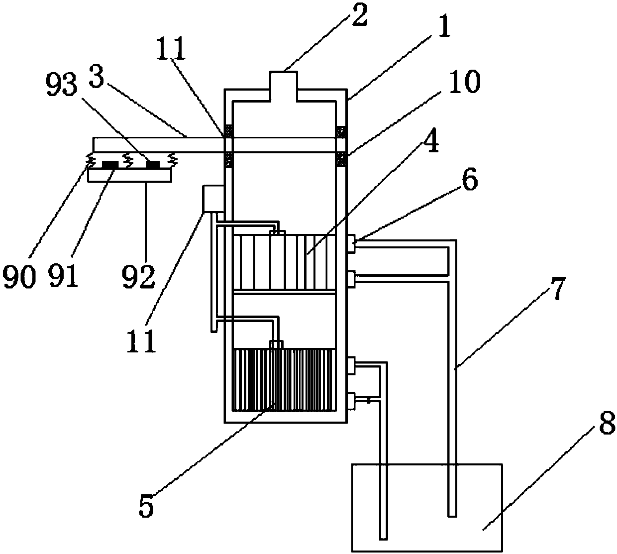
[0015] A composite multi-tube membrane ultrafiltration device for wastewater treatment, comprising a tank body 1 and a vibration device 9. The upper end of the tank body 1 is provided with a water inlet 2, and a dosing barrel 10 is installed on the side wall of the tank body 1. The dosing barrel 10 The upper ends of the microfiltration membrane 4 and the hollow fiber ultrafiltration ...


PUM


Abstract

The invention relates to the field of wastewater treatment in particular to a composite multi-pipe membrane ultrafiltration wastewater treatment device, which comprises a tank body and a vibration device, wherein the upper end of the tank body is provided with a water inlet; a chemical adding barrel is arranged on the side wall of the tank body; the chemical adding barrel respectively communicateswith a microfiltration membrane and a hollow fiber ultrafiltration membrane through pipelines; a filtering screen, a microfiltration membrane and a hollow fiber ultrafiltration filter ultrafiltrationmembrane are sequentially arranged in an inner cavity of the tank body from top to bottom; a clean water outlet is formed in the side wall of the hollow fiber ultrafiltration membrane and the microfiltration membrane, and is connected into a clean water pool through a water pipe; water outlets are formed under the microfiltration membrane and the hollow fiber ultrafiltration membrane. The composite multi-pipe membrane ultrafiltration wastewater treatment device has the advantages that the structure is simple; the wastewater is subjected to three-layer filtration; the clean water can be obtained after filtration; through the addition of the vibration device, the blockage of the filtering screen is prevented; the water filtration is convenient; through the addition of chemicals, the ultrafiltration membrane and the microfiltration membrane are subjected to anti-blockage treatment; the popularization is convenient.

Description

technical field [0001] The invention relates to the field of wastewater treatment, in particular to a composite multi-tube membrane ultrafiltration device for treating wastewater. Background technique [0002] Due to the rapid development of industry, the discharge of industrial wastewater is large, and the composition of industrial wastewater is complex, difficult to treat, and difficult to degrade and purify. At present, traditional solid-liquid separation technologies such as mechanical filters are usually used in the treatment of industrial wastewater. Such structures It has some shortcomings of large equipment volume, low production efficiency, low degree of automation and complicated operation, and the wastewater discharged after being limited by filtration accuracy may often exceed the standard. The ultrafiltration technology that has emerged in recent years has been widely used in the field of wastewater treatment. However, due to the high requirements of the ultrafi...

Claims


Application Information

Patent Timeline
IPC IPC(8): C02F9/02B01D61/14B01D65/08
CPCB01D65/08C02F1/001C02F1/444B01D2321/16B01D2311/2649B01D61/146
Inventor 詹延平刘丹芹
Owner FUJIAN YUEHUA ENVIRONMENTAL PROTECTION TECH CO LTD
Learn More